Optical module and methods for optically aligning and assembling the same

a technology of optical modules and optical resolution, applied in the field of optical modules, can solve problems such as degraded resolution, and achieve the effect of improving alignment precision and enhancing optical resolution of optical modules

Active Publication Date: 2007-09-18
UNIVERSAL SCIENTIFIC INDUSTRIAL (SHANGHAI) CO LTD
View PDF3 Cites 3 Cited by
  • Summary
  • Abstract
  • Description
  • Claims
  • Application Information

AI Technical Summary

Benefits of technology

[0006]Therefore, the object of the present invention is to provide an optical module and methods for optically aligning and assembling the same with improved alignment precision so as to result in an enhanced optical resolution of the optical module.

Problems solved by technology

Therefore, an overly large tolerance usually leads to optical misalignment, which results in over focus or under focus of the conventional optical module 1 such that the resolution thereof is degraded.

Method used


Image

  • Optical module and methods for optically aligning and assembling the same
  • Optical module and methods for optically aligning and assembling the same
  • Optical module and methods for optically aligning and assembling the same

Examples


Embodiment Construction

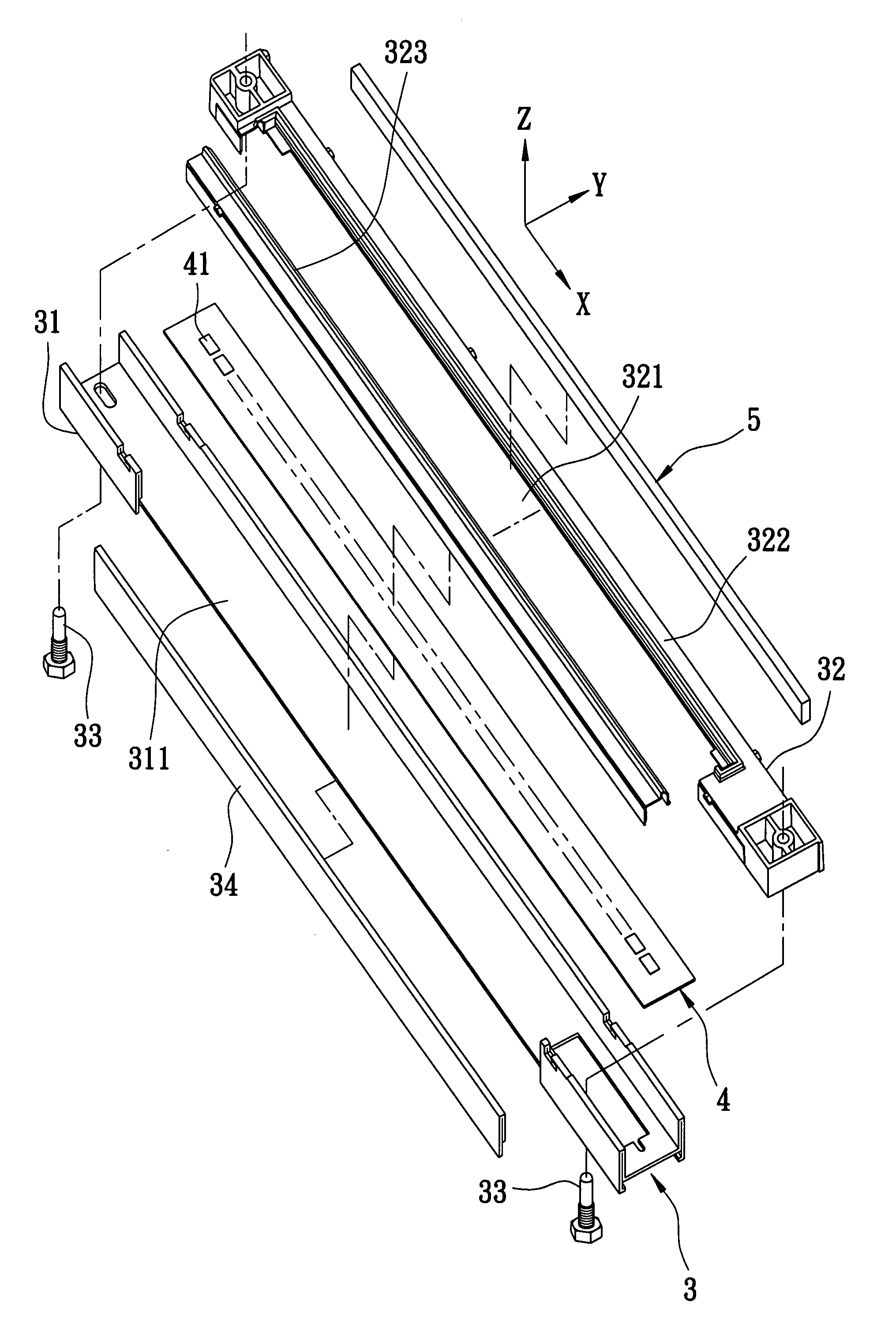
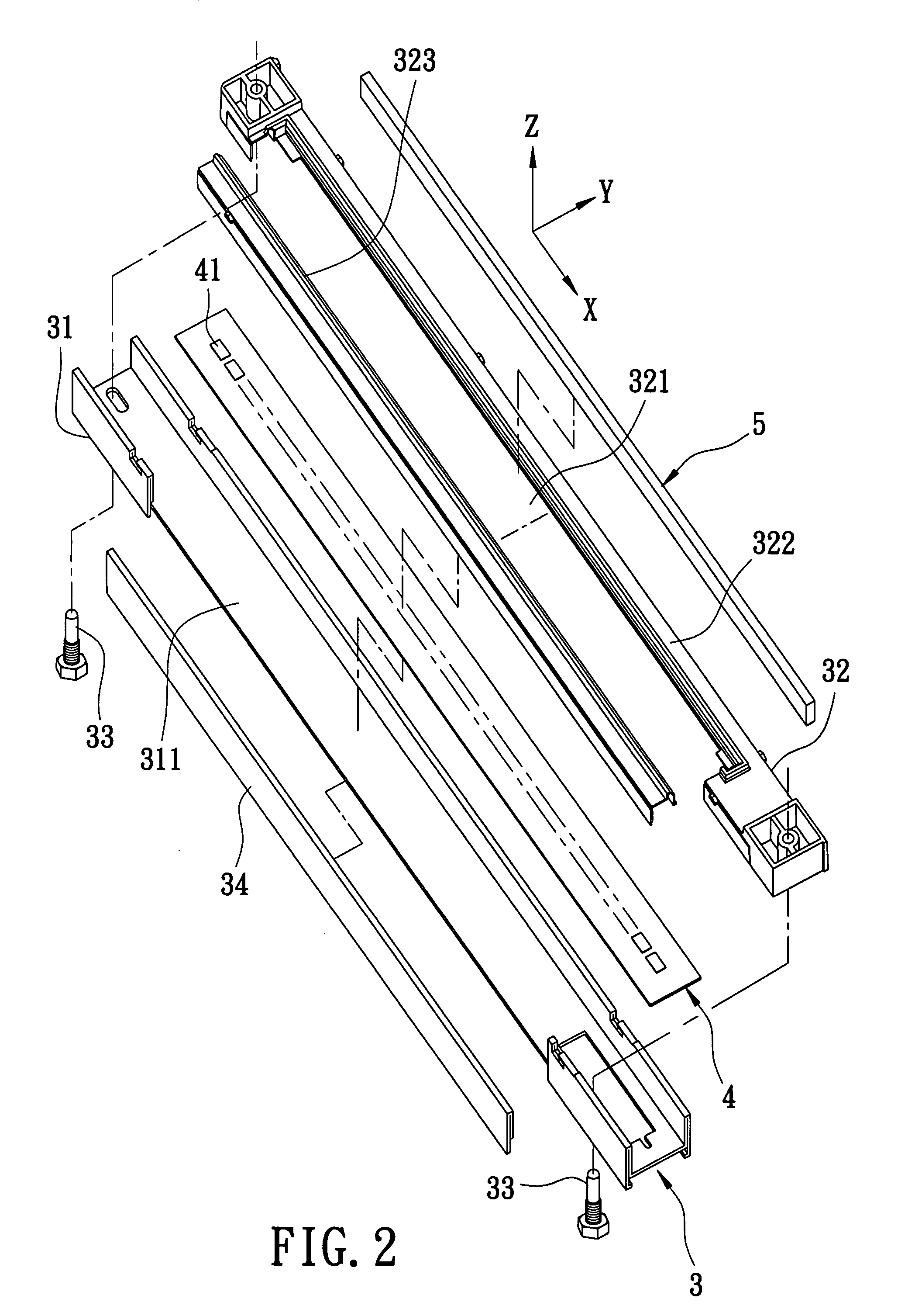
[0037]As shown in FIG. 2 and FIG. 3, the preferred embodiment of an optical module according to the present invention is for use in an optical input device, and is disposed to correspond in position to a glass plate 9 (as shown in FIG. 12). The glass plate 9 has a top surface 91 for supporting an object (not shown) . The optical module includes a housing unit 3, a light-sensing unit 4, and a lens unit 5.

[0038]The housing unit 3 includes an outer housing 31 extending along a first direction (X) and having an approximately U-shaped cross section, an inner support 32 extending along the first direction (X) and disposed in the outer housing 31, a pair of fasteners 33 for interconnecting the outer housing 31 and the inner support 32 respectively at opposite ends thereof, and a cover plate 34. The outer housing 31 is formed with a slot 311 in one side thereof, which extends along the first direction (X) .The inner support 32 includes first and second members 322, 323 coupled to each other...


PUM


Abstract

An optical alignment method is for an optical module including a housing unit, a light-sensing unit, and a lens unit. The method includes: (a) through image-capturing techniques, finding a light-sensing component of the light-sensing unit and a predetermined reference point, and determining an actual total optical path length between the light-sensing component and an object position; (b) subtracting a correction distance from the actual total optical path length to obtain a corrected total optical path length; (c) finding a first center line that divides the corrected total optical path length in half; (d) through image-capturing techniques, finding opposite first and second edges of the lens unit, and determining a lens length between the first and second edges; (e) finding a second center line that divides the lens length in half; and (f) assembling the lens unit to the housing unit such that the first and second center lines overlap.

Description

BACKGROUND OF THE INVENTION[0001]1. Field of the Invention[0002]The invention relates to an optical module. More particularly, the present invention relates to an optical module that is capable of sensing images, and to methods for optically aligning and assembling optical components of the optical module.[0003]2. Description of the Related Art[0004]As shown in FIG. 1, a conventional optical module 1 for an optical input device, such as a scanner, mainly includes a housing unit 11, a light-sensing unit 12, a lens unit 13, and a light-emitting unit 14. The housing unit 11 includes an outer housing 111 and a base 112 coupled to the outer housing 111. The outer housing 111 is formed with a groove 113. The light-sensing unit 12 includes a plurality of light-sensing components 121 aligned on top of the base 112. Each of the light-sensing components 121 is a Complementary Metal Oxide Semiconductor (CMOS) image sensor scanner. The lens unit 13 is embedded in the groove 113 in the outer hou...

Claims


Application Information

Patent Timeline
Patent Type & Authority Patents(United States)
IPC IPC(8): H01J40/14B41J2/45G03G13/04H04N1/04
CPCH04N1/0311H04N2201/02414H04N2201/02431H04N2201/02445H04N2201/02458H04N2201/02472H04N2201/02485H04N2201/02487
Inventor WU, MING-CHE
Owner UNIVERSAL SCIENTIFIC INDUSTRIAL (SHANGHAI) CO LTD
Why Eureka
Try Eureka