Gas-cooled electrical machine with pressure charging

a technology of electrical machines and gas-cooled electrical machines, which is applied in the direction of liquid fuel engines, magnetic circuit rotating parts, magnetic circuit shapes/forms/construction, etc., can solve the problems of high cost of external auxiliary devices, high cost of power and process control technology, and relatively high complexity, so as to improve heat dissipation and improve the effect of heat dissipation and effective cooling of the generator

Inactive Publication Date: 2007-09-18
ALSTOM TECH LTD
View PDF11 Cites 8 Cited by
  • Summary
  • Abstract
  • Description
  • Claims
  • Application Information

AI Technical Summary

Benefits of technology

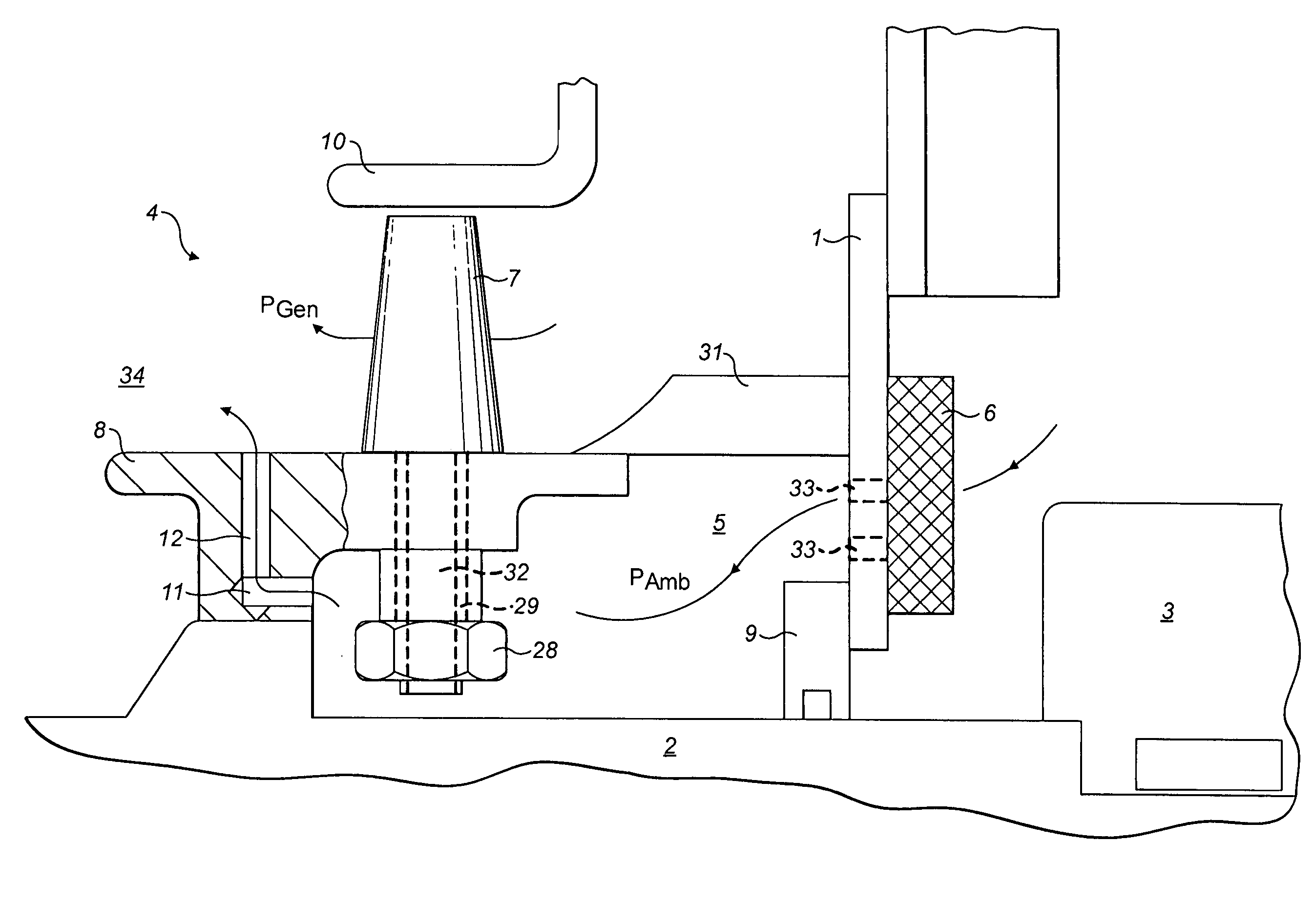
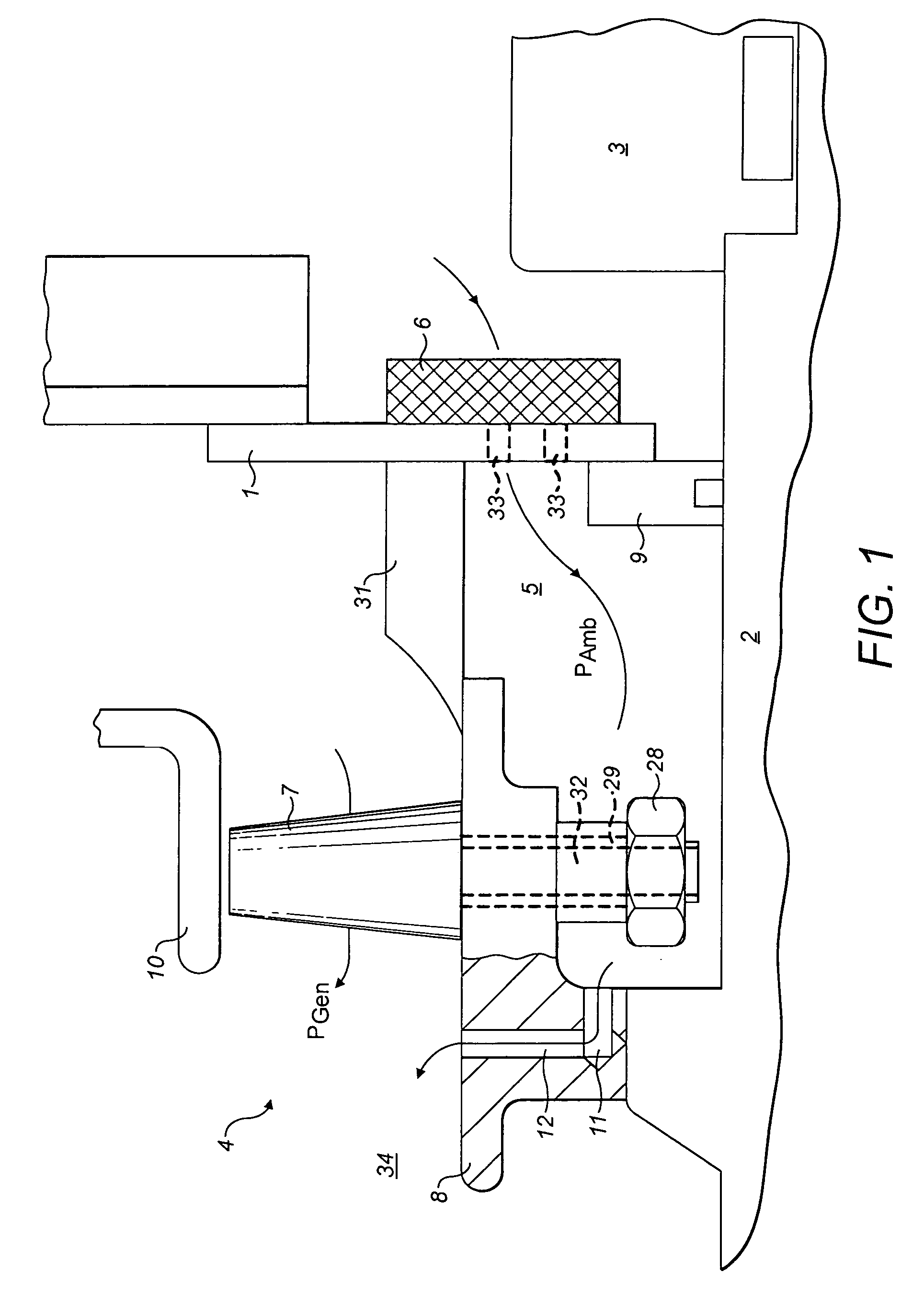
[0005]An objective of the present invention is to provide an improved gas-cooled electric machine that avoids that above-mentioned drawbacks of the state of the art. Moreover, a marked pressure increase is to be achieved in the generator housing so as to attain improved heat dissipation and thus more effective cooling of the generator. In this context, there should be no need for additional external devices to raise the pressure or for external control devices, but rather, a simple and inexpensive solution is to be provided that is also well-suited for easily retrofitting existing generators.

Problems solved by technology

The disadvantages here are the relatively high complexity and the high costs incurred for the external auxiliary devices, for the power and for the process-control technology.
Moreover, such an approach is somewhat malfunction-prone.

Method used


Image

  • Gas-cooled electrical machine with pressure charging
  • Gas-cooled electrical machine with pressure charging
  • Gas-cooled electrical machine with pressure charging

Examples


third embodiment

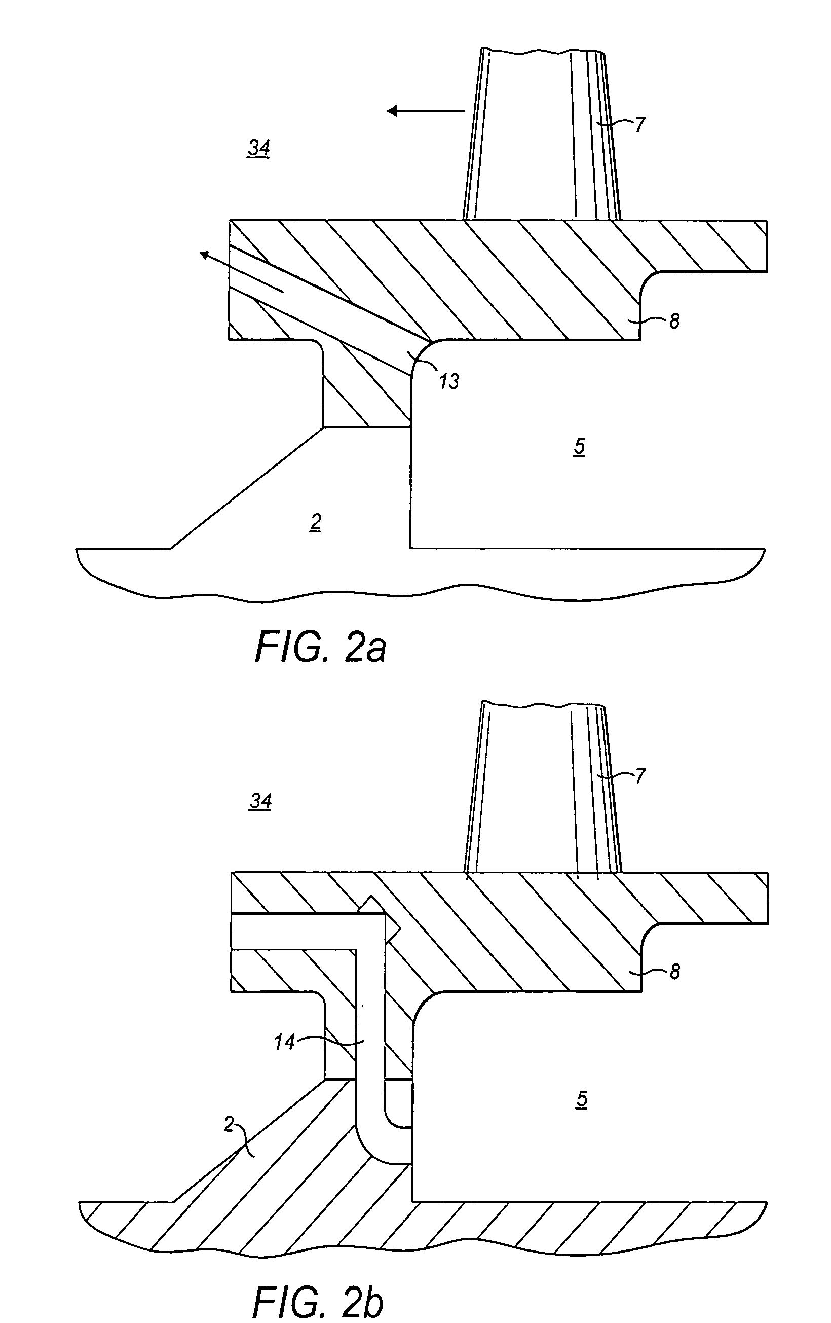
[0039]FIG. 2a shows a second advantageous embodiment of a pressure boosting means according to the invention, in which a diagonal passage bore 13 is made in the fan hub 8. As a result, the cooling air conveyed by the pressure boosting means into the generator interior 34 can flow out more favorably, which does not have negative impact on the flow coming off the fan blades 7. The same applies to the third embodiment depicted in FIG. 2b, in which there is a Z-shaped or double-L-shaped passage channel 14. Here, too, the flow is deflected, so that negative effects on the flow coming off the fan blades 7 are reduced. Here, the inlet side in the hub interior 5 lies on a smaller radius than the outlet side in the generator interior 34.

fourth embodiment

[0040]FIG. 3 shows a fourth embodiment in which the radius differential over the hub height is lengthened by means of a tubular sleeve 17 that is anchored in the fan hub 8 by means of a threaded bore 16 and that is connected to the hub interior 5 via a diagonal bore 15. In the embodiment according to FIG. 3, the tubular sleeve 17 is arranged on the trailing edge of the fan blades 7 and its height approximately matches the height of the fan blades 7. This likewise prevents disturbances on the flow coming off the fan blades 7, although the height of the tubular sleeve 17 can be varied here in such a way that the desired increase in the absolute pressure in the generator interior 34 can be achieved.

[0041]FIG. 4a shows a fifth advantageous embodiment of the present invention and FIG. 4b shows a sectional view in the arrow direction along an intersection line IV-IV in FIG. 4a. Here, on the trailing edge of the fan blade 7, there is a tubular sleeve 21 with a streamlined jacket 18 or an a...


PUM


Abstract

A gas-cooled electric machine includes a generator housing, a rotor shaft, at least one axial fan disposed on the rotor shaft inside the generator housing and having a hub, and a pressure boosting apparatus associated with the axial fan and configured to raise an absolute pressure in a generator interior. The pressure boosting apparatus has at least one flow channel between an interior of the hub and the generator interior and is at least partially delimited by the hub. A flow inlet into the flow channel and a flow outlet out of the flow channel are disposed radially at a distance with respect to each other.

Description

[0001]The present invention relates to a gas-cooled electric machine, particularly to an air-cooled turbo-generator with a closed coolant circulation system, having a rotor shaft on which there is at least one axial fan inside a generator housing.BACKGROUND[0002]As is generally known, turbo-generators for generating three-phase current are powered by steam or gas turbines. As a rule, the rotor of a turbo-generator consists of a solid cylindrical forged body made of steel in which the excitation winding is distributed over individual slots. The rotor turns in the bore of the stator of a generator. The stator consists of a sheet metal body which, in turn, has slots to accommodate the armature winding. The decisive factor in the configuration and construction of such turbo-generators is the cooling technology, since this makes it possible to substantially raise the output. Today's turbo-generators often work with a gaseous coolant and with fans that are arranged on the rotor and that c...

Claims


Application Information

Patent Timeline
Patent Type & Authority Patents(United States)
IPC IPC(8): H02K9/04H02K9/06
CPCH02K9/06
Inventor JOHO, REINHARD
Owner ALSTOM TECH LTD
Why Eureka
Try Eureka