Electronic device, transmission system, and method for determining connection condition

a transmission system and electronic device technology, applied in the field of electronic devices, can solve problems such as short-circuit protection circuits

Inactive Publication Date: 2007-09-18
SONY CORP
View PDF9 Cites 7 Cited by
  • Summary
  • Abstract
  • Description
  • Claims
  • Application Information

AI Technical Summary

Benefits of technology

[0030]Also, in the infrared optical transmission apparatus 200A shown in FIGS. 1 and 2, even if the infrared optical transmission unit 300 is connected, an infrared signal SIR that corresponds to the modulated RF signal MRF is output from the infrared optical transmission section 201, thereby dissipating power wastefully, or accelerating deterioration in the infrared optical transmission section 201.
[0039]For example, in the third condition, a warning of short-circuit problem is given. This notification is made by use of a display, by means of methods such as the production of a voice from a speaker, by the light emission from a light-emitting element, and by production of a buzzer sound. This allows a user to be easily apprised of the short-circuit problem in the connector, and to take any remedial actions.
[0041]Accordingly, if no external device is connected to the connector, an output signal that corresponds to an input signal is output from the second signal transmission section that is built in an electric device. In contrast, if an external device is connected to the connector, the output signal that corresponds to the input signal is output from the first signal transmission section in this external device, and no signal is output from the first signal transmission section built in the electronic device. This avoids the occurrence of a situation of wasteful power dissipation in which output signals are simultaneously output from the first signal transmission section in the external device and from the second signal transmission section that is built in the electronic device.

Problems solved by technology

Therefore, a short-circuit problem may cause a short-circuit protection circuit equipped with the regulator 202 to operate, or the destruction of, or failures such as burnout in the RF cut-off inductor 210 or a printed circuit board pattern.
Further, this Japanese publication has not disclosed how a DC power supply voltage to a connector which is provided with a modulated RF signal on which a DC power supply voltage is superposed can be controlled on the basis of whether or not the infrared optical transmission unit is connected to the connector.

Method used


Image

  • Electronic device, transmission system, and method for determining connection condition
  • Electronic device, transmission system, and method for determining connection condition
  • Electronic device, transmission system, and method for determining connection condition

Examples


Embodiment Construction

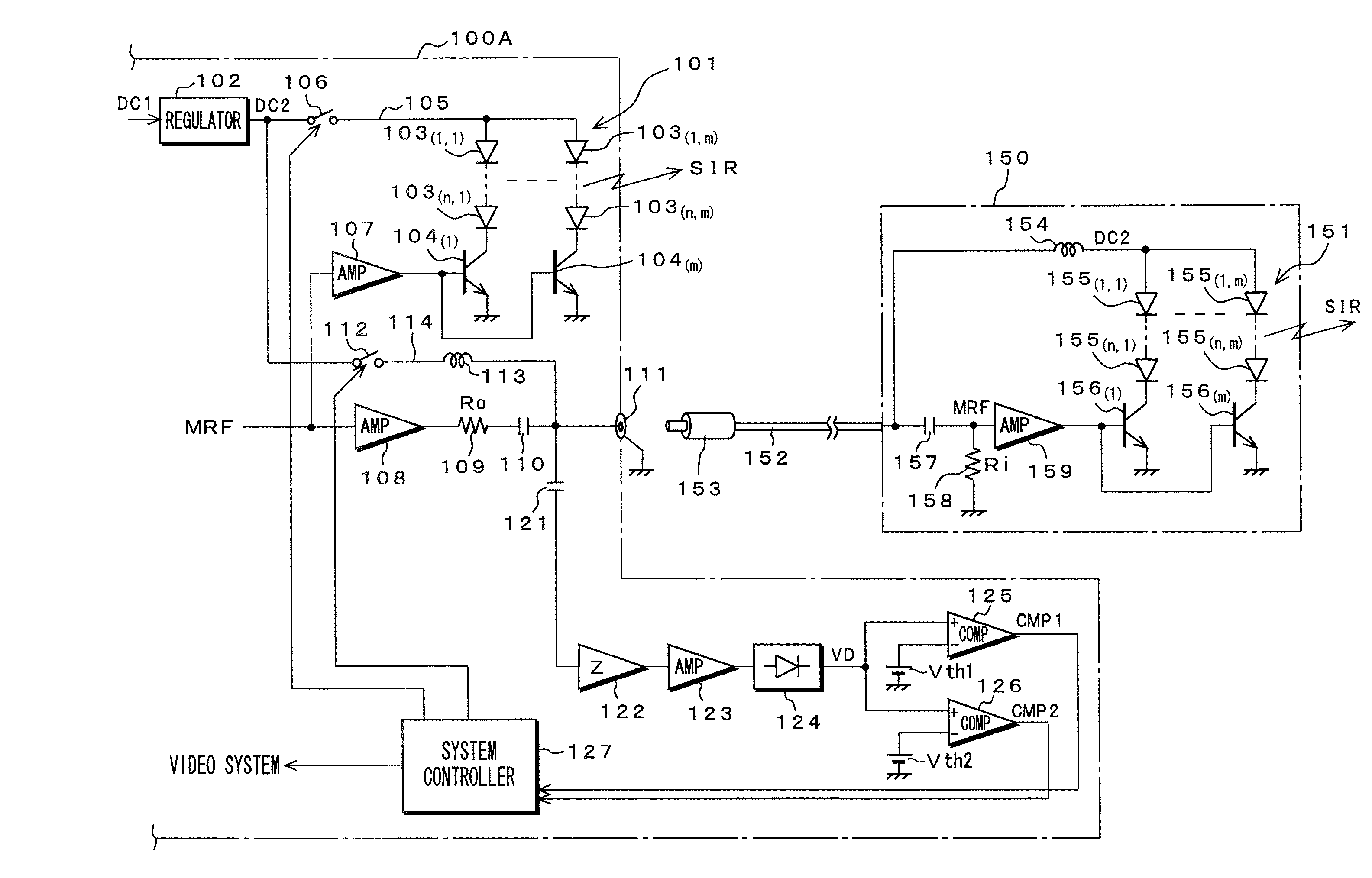
[0053]The following will describe a first embodiment of the present invention. FIG. 5 shows a configuration of an infrared optical transmission apparatus 100A according to the first embodiment.

[0054]A DC power supply voltage DC1 of, for example, 12V obtained from a power supply circuit, not shown, is supplied to a regulator 102 from which a stabilized DC power supply voltage DC2 of, for example, 9V is obtained.

[0055]An output side of the regulator 102 is connected to a collector of an NPN driver transistor 104(1), whose emitter is grounded, through a series circuit constituted of infrared light-emitting diodes 103(1, 1) through103(n, 1). The output side of the regulator 102 is also connected to a collector of an NPN driver transistor 104(m), whose emitter is grounded, through a series circuit constituted of infrared light-emitting diodes 103(1, m) through 103(n, m). Herein, n=3 and m=4, for example, are used. These n times m number of infrared light-emitting diodes 103(1, 1) through...


PUM


Abstract

An electronic device has a first signal path, a first power supply path, and a connector that transmits to an external device the input signal on which the voltage has been superposed. The device also has a first power supply switch inserted into the first power supply path and an amplitude detector that detects at the connector an amplitude of the input signal, a control section that determines, based on a detection output from the amplitude detector, which a connection condition of the external device to the connector is a first condition in which the external device is not connected to the connector or a second condition in which the external device is connected to the connector. Based on the connection condition, the control section turns on or off the first power supply switch.

Description

CROSS REFERENCE TO RELATED APPLICATION[0001]The present invention contains subject matter related to Japanese Patent Application JP 2005-311620 filed in the Japanese Patent Office on Oct. 26, 2005, the entire contents of which being incorporated herein by reference.BACKGROUND OF THE INVENTION[0002]1. Field of the Invention[0003]The present invention relates to an electronic device equipped with a connector for connecting an external device so as to supply, through the connector, the external device with a signal on which voltage is superposed; a transmission system for transmitting an output signal corresponding to an input signal from any signal transmission sections with which the external device and the electronic device are provided; and a method for determining a connection condition between the connector of the electronic device and the external device.[0004]2. Description of Related Art[0005]FIG. 1 shows an infrared optical transmission apparatus 200A as related art. This inf...

Claims


Application Information

Patent Timeline
Patent Type & Authority Patents(United States)
IPC IPC(8): G01R31/04G01R19/00G01R31/08H04Q1/24H04B10/11H04B10/03H04B10/07H04B10/80
CPCH04B3/548H04B2203/547
Inventor TAKANO, TAKASHI
Owner SONY CORP
Why Eureka
Try Eureka