Rotational display system

a display system and rotating technology, applied in the field of rotating display systems, can solve the problems of inconvenient mass production, inconvenient operation, and inability to meet the needs of large-scale production, and achieve the effects of high optical quality, low cost, and high quality

Active Publication Date: 2007-09-18
SPIN SCREEN INC
View PDF12 Cites 33 Cited by
  • Summary
  • Abstract
  • Description
  • Claims
  • Application Information

AI Technical Summary

Benefits of technology

[0030]The present invention provides a system which integrates unique lighting technologies, switching systems, mounting systems, information delivery systems and power supply systems within a vehicular wheel to provide an advanced, high quality visual display apparatus. These technologies, and their many unique applications, provide for a novel and useful series of video display devices that are small, lightweight, efficient and have the capability of producing a clear, bright, high definition image that is equivalent to that of a modern day TV or high quality computer monitor. Further applications of the disclosed technologies allow the installation of compact rotary video displays in numerous applications where rotating portions of machinery are equipped with the disclosed technologies to display visual images, videos and text while rotating. The compact, energy efficient, high optical quality technology disclosed herein is relatively inexpensive to mass produce and can be applied to many unusual locations. The primary application for rotational scanning systems discussed herein is an electronically controlled display system disposed upon or made integral to a motor vehicle wheel with both ornamental and functional applications.

Problems solved by technology

Such improvements rendered rotary image display systems obsolete.
The illumination systems, propulsion means, synchronization circuits and power requirements of rotary mechanical visual display systems made them heavy, bulky, inefficient, unreliable and of marginal value due to low video quality when compared to cathode ray tube visual displays.
However, because the device derives both a positional reference point and data concurrently as a predetermined point on the rotating arm passes the infrared sender, the amount of data that can be transferred is very limited.
Thus, Lo's device is limited to displaying alpha-numeric data, caller ID information, clock settings and a series of pre-determined greetings through a telephone interface.
Lo's design does not disclose hardware, systems, methods or other provisions capable of providing motion picture sequences that are user selected, or supplied though an external source such as a digital media system, DVD, hard drive or other data storage device.
Moreover, like the other existing prior art, the system is monochromatic, and thus has support circuitry that limits data and image display throughput to the monochromatic color output of the included display devices.
Thus, its hardware and software cannot support streaming color video to display life like color images or color full motion video since the system is not wired and programmed to support true color synchronized switching or related data throughput.
Because the system described by Chernick is primarily designed to be a very affordable children's toy, it is not capable of the advanced requirements necessary to display true color synchronized switching.
While this system employs rotational scanning, images displayed contain little or no parameters for user selectability, and are incapable of displaying life like color images or color full motion video.
While compass based positional synchronization works very well for devices which rotate in a horizontal plane, a traditional compass based system will not provide adequate positional synchronization for devices which rotate in vertical or near vertical planes.
In addition, proximity to various metals, magnetic fields, and radio frequency interference from cellular phones, vehicle electronics and other high frequency sources also interferes with compass function via direct magnetic field distortion or by subsequent inductive jamming of sensitive compass support circuitry.
This confuses positional synchronization, and thus would corrupt and distort the images output on the illuminated array, making the device unsuitable for use in conjunction with vehicles and / or vehicle wheels.
These technical challenges include construction of rotating displays, selection of appropriate high brightness LEDs for monochromatic displays, proper balance and vibration control of rotating displays, methods of delivering reliable electrical power to the rotating portion of displays, methods and hardware for position sensing on the display, data delivery for displaying images on rotating arrays, programmable integrated circuit (PIC) programming and related costs.
While all of the prior art devices are capable of providing relatively simple displays, none of the prior art devices are capable of providing true color or streaming video.
However, the devices can be difficult to read and render the possibility of full motion video displays across the entire virtual disk impossible.
Still yet, the geometry of all prior planar display devices have some object or component mounted at the center of the circle of rotation that blocks the presence of illuminating elements.
Simply put, if the center does not have illumination hardware, any image programmed to intersect the center of the circle would not display properly.
This same limitation also affected the quality of early scanning image systems, like those of Nipkow and Baird.
Further yet, the prior art does not disclose or suggest a rotational display device which operates in conjunction with a motor vehicle.

Method used


Image

  • Rotational display system
  • Rotational display system
  • Rotational display system

Examples


Embodiment Construction

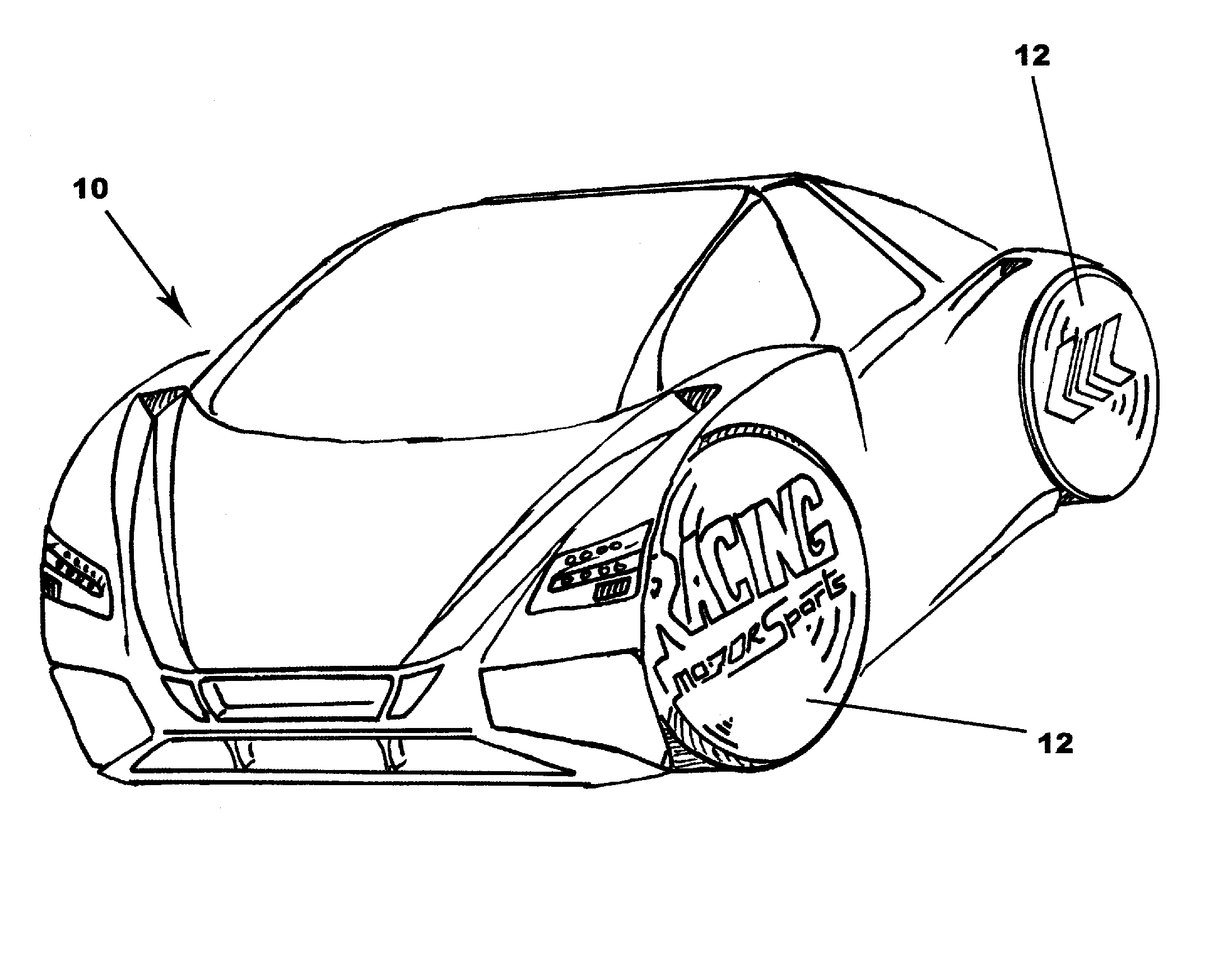
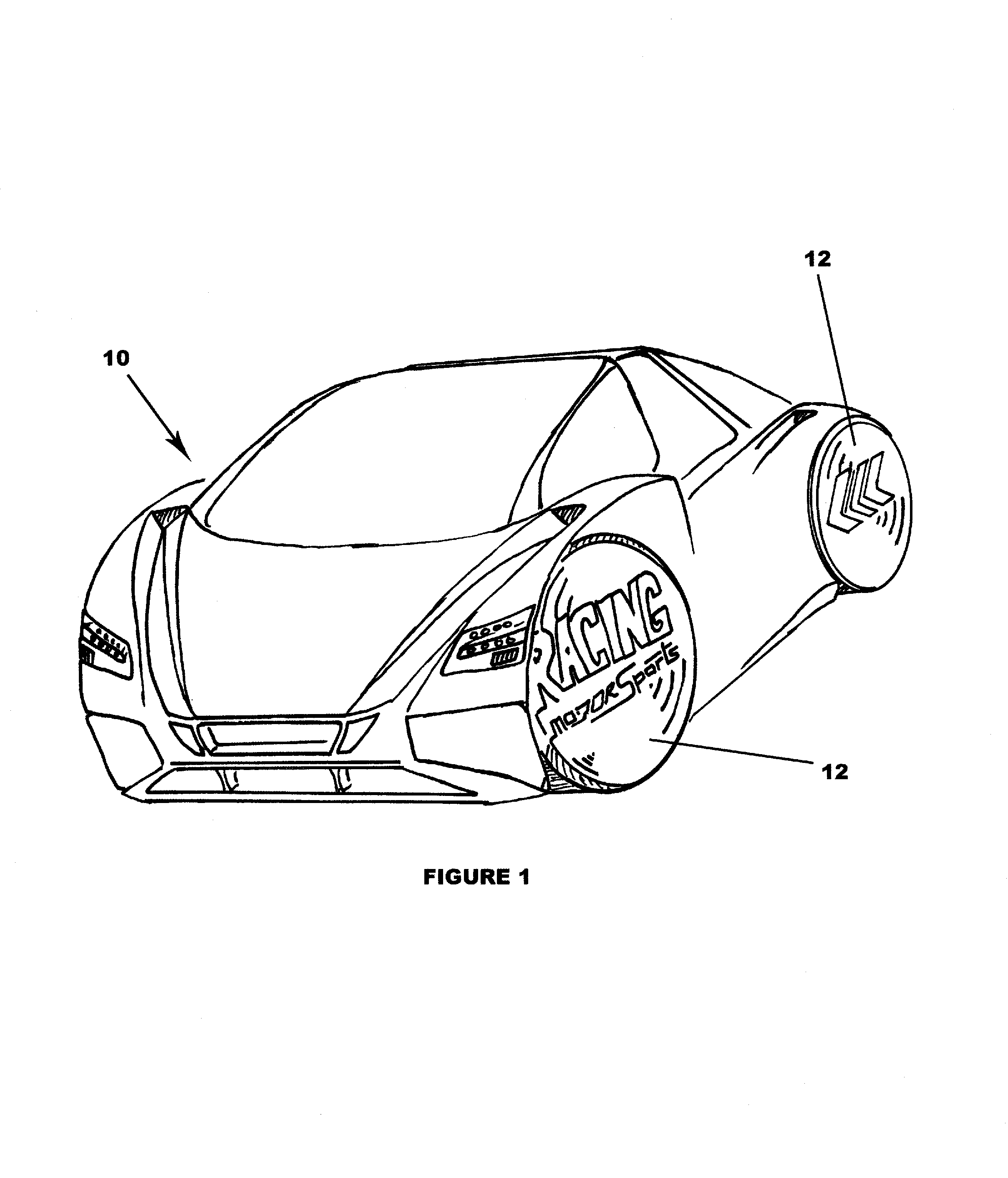
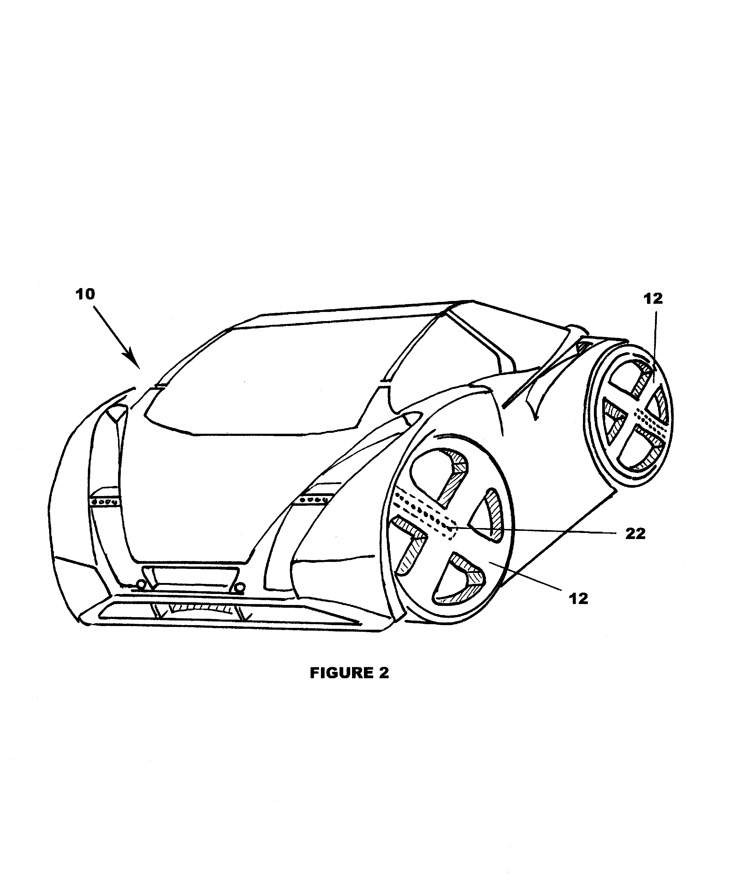
[0046]While the present invention is susceptible of embodiment in various forms, there is shown in the drawings and will hereinafter be described a presently preferred embodiment with the understanding that the present disclosure is to be considered an exemplification of the invention and is not intended to limit the invention to the specific embodiments illustrated.

[0047]Referring to FIGS. 1-10, various embodiments of the instant invention are illustrated as being incorporated into the wheels of a motor vehicle 10. In general, the disclosed systems are rotational display systems 12 that display user selectable visual information such as images, text, numbers, symbols, animations, videos and the like upon the wheel of a vehicle during rotation thereof. It is important to note that the component description below is a general way to explain the system and its' basic components. Given modern technology, many or all of the components could be combined or split in many ways and thus sho...


PUM


Abstract

The present invention provides a system which integrates unique lighting technologies, switching systems, mounting systems, information delivery systems and power supply systems within a vehicular wheel to provide an advanced, high quality visual display apparatus. These technologies, and their many unique applications, provide for a novel and useful series of video display devices that are small, lightweight, efficient and have the capability of producing a clear, bright, high definition image that is equivalent to that of a modern day TV or high quality computer monitor.

Description

FIELD OF THE INVENTION[0001]This application claims priority under 35 USC 119(e) to the Provisional Patent Application No. 60 / 589,651, filed Jul. 21, 2004.[0002]This invention relates generally to automotive lighting systems. More specifically, the present invention relates to the display of visual images and / or display of visual information such as pictures, text and full motion video sequences on the rotating wheels of a vehicle.BACKGROUND OF THE INVENTION[0003]Numerous systems for producing visual images and displaying visual information such as pictures, text and full motion video sequences were developed over a century ago. One such technology developed utilizes rotating assemblies having intermittently illuminated elements to produce text or basic shapes. The rotation, combined with rapidly changing illuminated segments produces a series of flashing frames that blend to form a recognizable image, or series of images. This effect is broadly known as persistence of vision and is...

Claims


Application Information

Patent Timeline
Patent Type & Authority Patents(United States)
IPC IPC(8): G09G5/00
CPCB60K35/00B60K37/06G09F21/045G09G3/005B60K2350/1024B60K2350/1028B60K2370/143B60K2370/1438
Inventor GILBERT, MARK
Owner SPIN SCREEN INC
Why Eureka
Try Eureka