System and method for an adaptive morphology x-ray beam in an x-ray system

a technology of adaptive morphology and beams, applied in the field of xray imaging systems, can solve the problems of insufficient contrast of shadow images for features in objects, requiring much less dose to be imaged adequately, and affecting the quality of x-ray images, etc., and achieves a wide range of gradation levels.

Active Publication Date: 2007-09-18
GENERAL ELECTRIC CO
View PDF20 Cites 40 Cited by
  • Summary
  • Abstract
  • Description
  • Claims
  • Application Information

AI Technical Summary

Benefits of technology

[0024]The present invention also provides for a system and method for “x-ray dodging,” a technique for automatic and dynamic spatial modulation of an x-ray beam based on a beam intensity signal. X-ray dodging consists of placing arrangements of x-ray-blocking elements in the beam. Some of the elements may overlap to various degrees thus varying the areas of the blocked portions of the beam. The entire arrangement is then caused to undergo a high-frequency periodic motion while the beam intensity is caused to vary in time in synchronization with the periodic motion. The combined effect of this process smoothens the blocked portions of the beam to result in a continuously varying smooth semitransparent attenuations pattern with a high number and range of gradation levels.

Problems solved by technology

Several fundamental problems exist in this conventional approach.
If a beam striking an object volume with a large radiographic thickness has insufficient intensity to allow a sufficient number of x-ray photons to reach the detector, then the resultant shadow image may not produce sufficient contrast for features in the object volume.
However, the high x-ray doses also strike object volumes with smaller radiographic thicknesses, which require much less dose to be imaged adequately.
Excessive exposures of the thin object volumes may be harmful.
In addition they may cause additional imaging problems, such as, for example, (a) increased x-ray scatter, (b) increased veiling glare, and (c) detector saturation.
However, such systems may still expose object volumes with smaller radiographic densities to unnecessarily large x-ray doses.
In addition, such high-performance detectors add considerable expense to an x-ray system.
Another problem with conventional x-ray imaging are high doses to object volumes imaged for reference only without the need for high spatial and grayscale resolution.
Another problem with conventional fluoroscopy is excessive exposure rates to object volumes where little change occurs from frame to frame and, therefore, little new information is present.
However, as many x-ray procedures may require hundreds or thousands of continuous frames from multiple views, these solutions do not provide a mechanism for uninterruptible point-and-shoot imaging with optimized beam modulation.
Addressing the problem with specialized filters that work with low- and high-energy beams would require a substantial increase in the complexity of such systems.
For such systems to provide meaningful beam modulating factors in a wide range of x-ray techniques, their designs may be prohibitively complex.
In addition, automated beam modulation systems proposed in above references may be too bulky, slow, and expensive to provide high speed, resolution, and dynamic range that would make them useful in a wide spectrum of imaging applications.

Method used


Image

  • System and method for an adaptive morphology x-ray beam in an x-ray system
  • System and method for an adaptive morphology x-ray beam in an x-ray system
  • System and method for an adaptive morphology x-ray beam in an x-ray system

Examples


Embodiment Construction

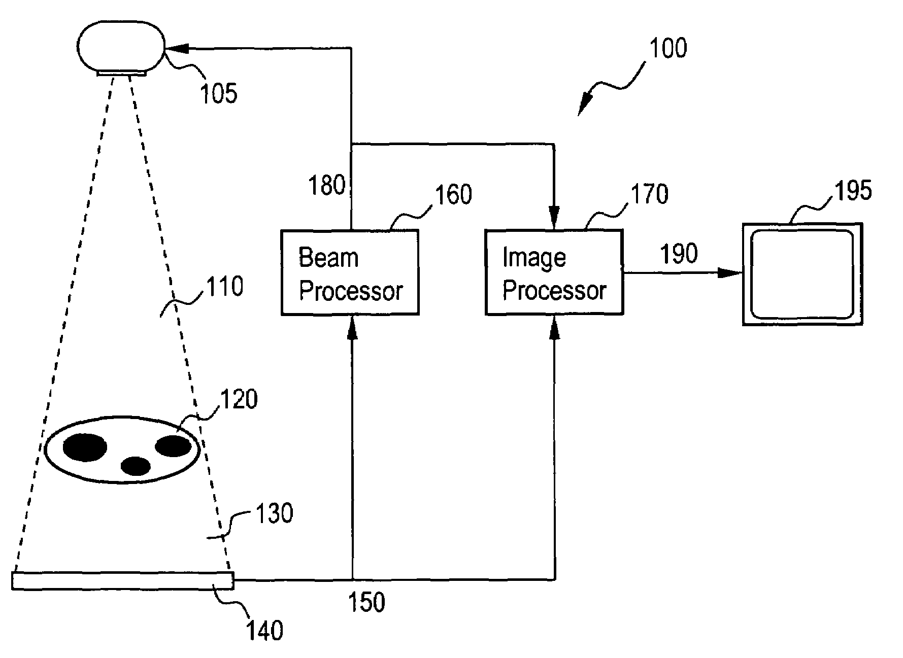
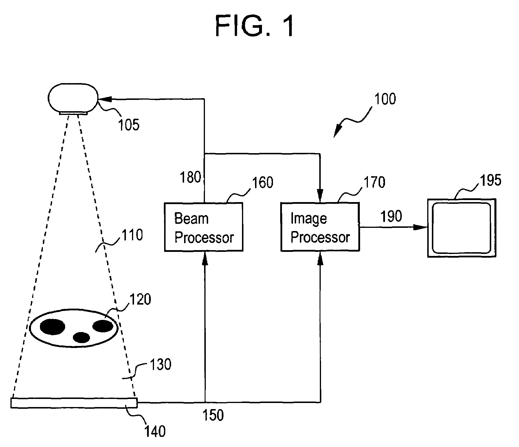
[0036]FIG. 1 illustrates a schematic diagram on an x-ray system 100 using x-ray beam modulation in accordance with an embodiment of the present invention. System 100 includes an x-ray source 105 producing a spatially modulated beam 110, an imaged object 120, an x-ray detector 140, an x-ray beam processor 160, an image processor 170, and a display device 195. Modulated beam 110 passes through imaged object 120, is attenuated to various degrees by its features, and forms residual beam 130. Detector 140 measures the beam intensities in the residual beam 130 and communicates a residual image 150 to the beam processor 160 and the image processor 170. A beam intensity signal 180 can be communicated from the beam processor 160 to the x-ray source 105 and to the image processor 170. The image processor produces a displayed image signal 190 and communicates to display device 195.

[0037]As mentioned above, source 105 is capable of transmitting a spatially modulated beam 110 towards imaged obje...


PUM


Abstract

The present invention provides for an x-ray system and method using dynamic automated spatial modulation of an x-ray beam. The system includes an x-ray source transmitting a spatially modulated beam towards an object to be imaged, an x-ray detector receiving the beam and measuring a plurality of intensities across the beam, a beam processor controlling the beam intensity profile, and an image processor producing an output image signal. The detector produces a residual image based on at least the intensities measured at the detector. The beam intensity profile may be based on at least some of the following: (a) the residual image from the x-ray detector, (b) current beam intensities, (c) regions on interest in the image, and (d) predicted or measured object motion in the image. The system's output image is based on one or more of said residual image and said beam intensity signal.

Description

BACKGROUND OF THE INVENTION[0001]The present invention generally relates to an x-ray imaging system. In particular, the present invention relates to a system and method for x-ray imaging with spatial modulation of the x-ray beam.[0002]Conventional x-ray imaging systems consist of an x-ray source exposing an object to an essentially uniform x-ray beam. As the beam passes through the object, varying radiographic densities throughout the object cause varying portions of x-ray flux to be attenuated (for example, absorbed or scattered) in the object. After passing through the object, the remaining beam strikes a detector. As the detector receives the beam with varying intensities, the detector measures and communicates the beam intensities to a data acquisition system. The data acquisition system may then use the beam intensities to create a shadow image.[0003]Several fundamental problems exist in this conventional approach. For example, the entirety of the imaged object receives a relat...

Claims


Application Information

Patent Timeline
Patent Type & Authority Patents(United States)
IPC IPC(8): G21K1/00G21K3/00H05G1/64
CPCA61B6/032G21K1/10A61B6/542A61B6/4035A61B6/00
Inventor YATSENKO, DIMITRI VICTOROVICHANDERTON, RICHARD LARRY
Owner GENERAL ELECTRIC CO
Why Eureka
Try Eureka