Creation of an object within an object hierarchy structure

a technology of object hierarchy and object hierarchy, applied in the direction of user interface execution, data acquisition and logging, instruments, etc., can solve the problems of difficult to discover how to perform an operation, the conventional object hierarchy scheme has not kept pace with the ever increasing demands placed on computer users to work faster, and the creation of a new object within an object hierarchy is historically a counterintuitive process

Active Publication Date: 2007-09-18
SZ DJI TECH CO LTD
View PDF65 Cites 176 Cited by
  • Summary
  • Abstract
  • Description
  • Claims
  • Application Information

AI Technical Summary

Benefits of technology

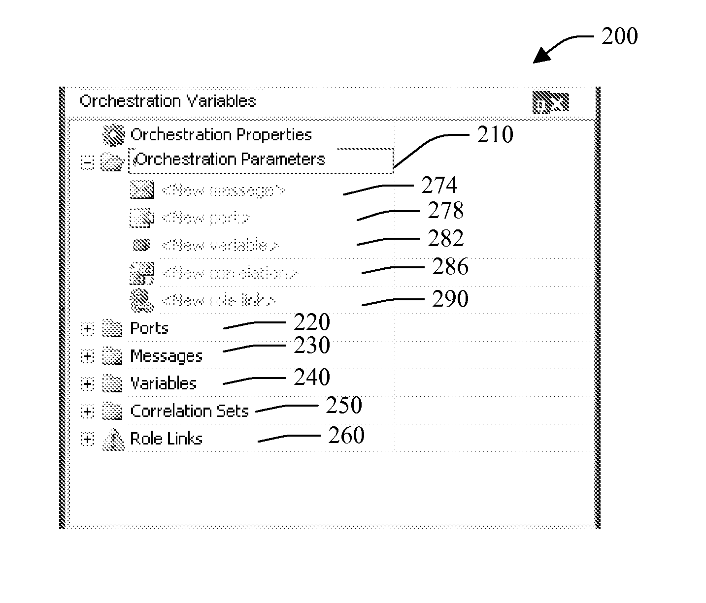
[0011]Yet another aspect of the present invention provides for a user interface which can serve as a dynamic modeless wizard that is in-line within an object hierarchy. A “wizard” in the sense that it is a process that is initiated, guides the user and collects data for the operation, executes zero or more sub-operations (work items), and has a finish point; “modeless” in that the user can modify one parameter value but not the others and come back at a later time; “dynamic” in that the steps to take (e.g., the work items to perform) to complete the entire operation are automatically generated; “in-line” in that you don't have to do any context switching to some other user interface like a separate dialog box or nearby modeless tool window.

Problems solved by technology

Creating a new object within an object hierarchy, however, has historically been a counterintuitive process.
Although highly useful, such conventional object hierarchy scheme has not kept pace with the ever increasing demands placed on computer users to work faster and concurrently handle greater amounts of file and application types.
Discoverability of how to perform an operation has often times been a confusing and daunting task for user(s).
This has been overburdening to the user.

Method used


Image

  • Creation of an object within an object hierarchy structure
  • Creation of an object within an object hierarchy structure
  • Creation of an object within an object hierarchy structure

Examples


Embodiment Construction

[0039]The present invention is now described with reference to the drawings, wherein like reference numerals are used to refer to like elements throughout. In the following description, for purposes of explanation, numerous specific details are set forth in order to provide a thorough understanding of the present invention. It may be evident, however, that the present invention may be practiced without these specific details. In other instances, well-known structures and devices are shown in block diagram form in order to facilitate describing the present invention.

[0040]As used in this application, the term “computer component” is intended to refer to a computer-related entity, either hardware, a combination of hardware and software, software, or software in execution. For example, a computer component may be, but is not limited to being, a process running on a processor, a processor, an object, an executable, a thread of execution, a program, and / or a computer. By way of illustrat...


PUM


Abstract

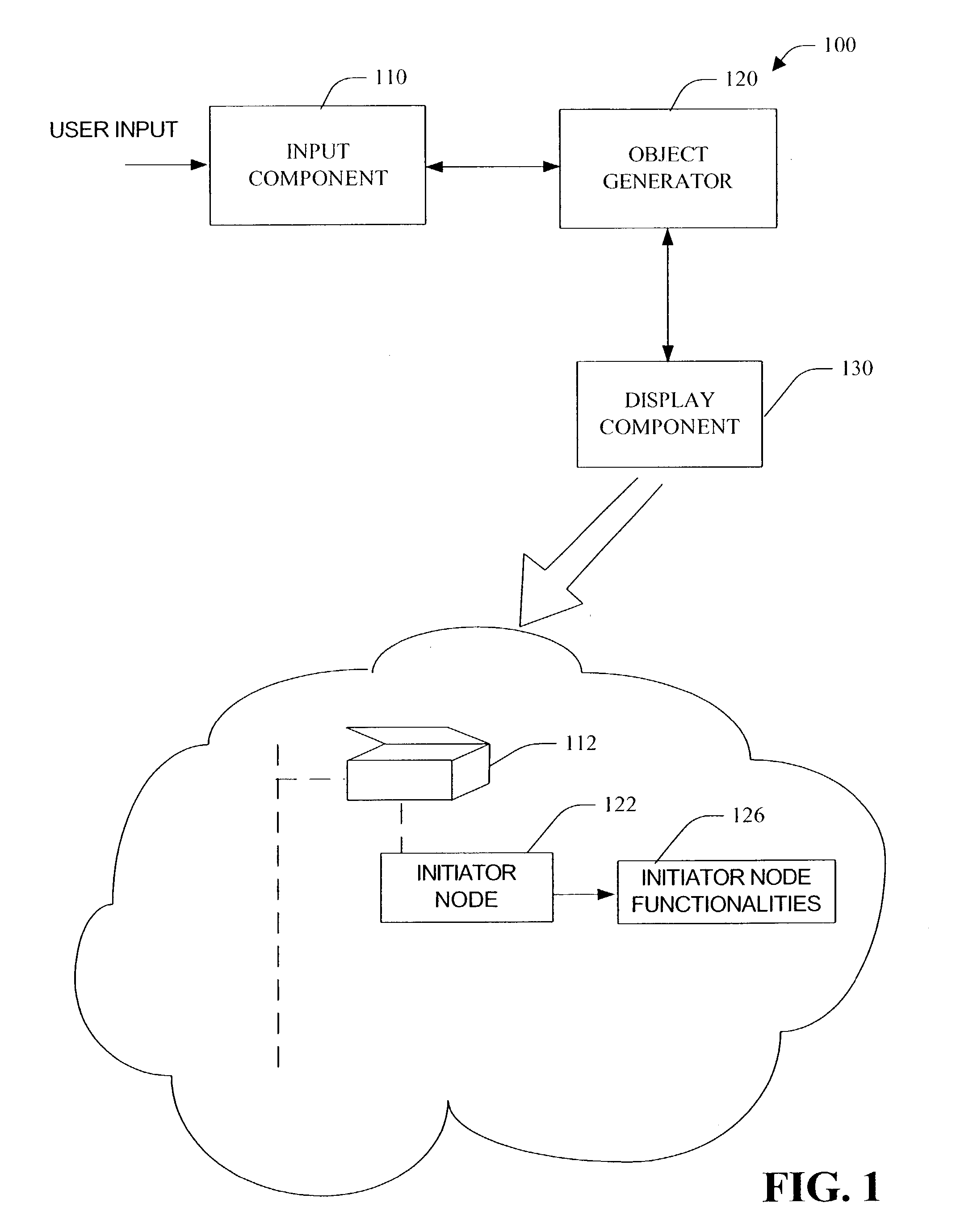
An object generator provides for creation of object(s) in an object hierarchy structure. In response to a command to expand a node/object, the object generator provides an initiator node that facilitates generation of a new object within the object hierarchy upon expansion of the node. A display component concurrently displays the initiator node with the expanded node. The initiator node used for creating objects placed (e.g., in-line) within an object hierarchy structure. To create a new object, an instruction (e.g., user input) to expand a node having a initiator node is received. By selecting the initiator node and entering a name, an object of type defined by the initiator node is created. For example, once the object is created the user can enter information defining parameter(s) of the object. Information can be entered through a user interface box (e.g., text box) that is displayed upon the creation of the object. Also, a grid can overlay the object hierarchy structure allowing information to be entered directly into grid cell(s). The grid can further be employed to display defined parameter(s).

Description

TECHNICAL FIELD [0001]The present invention generally relates to creation of object(s) in a computer system. In particular, the present invention relates to a system and method for the creation of object(s) within an object hierarchy structure.BACKGROUND OF THE INVENTION[0002]An object hierarchy structure, such as a computer tree, allows a user to quickly navigate through the hierarchy structure. Object hierarchies generally include parent node(s), which can be expanded, and child node(s) (e.g., that represent or map to real-world object(s)) that can be found within those parent nodes. A user can expand a parent node to view the contents of that node, or compress a parent node when the contents of the parent node are no longer need be visible. The nodes can correspond to objects of a variety of data types as well as application types. For example, base nodes as well as child nodes correspond to file or application directories, and the contents therein can be documents, media, applic...

Claims


Application Information

Patent Timeline
Patent Type & Authority Patents(United States)
IPC IPC(8): G06F9/44G06F12/00G06F17/40
CPCG06F9/4443G06F9/451B27B23/00E02F3/96
Inventor ISHIMITSU, MICHAEL KAZUOSTALLO, GIOVANNI
Owner SZ DJI TECH CO LTD
Why Eureka
Try Eureka