Double flow cage compactor dryer apparatus and method of compacting and drying wastes

a dryer and compactor technology, applied in drying, lighting and heating equipment, and stationary filter elements, etc., can solve the problems of urban solid waste disposal, environmental drawbacks, and more difficult to find new areas, so as to improve the resistance of the device, reduce the time, and reduce the effect of heat transmission

Inactive Publication Date: 2007-09-25
LA GIOIA ANTONIO
View PDF9 Cites 10 Cited by
  • Summary
  • Abstract
  • Description
  • Claims
  • Application Information

AI Technical Summary

Benefits of technology

[0026]To obtain the above objects, it is suggested according to the present invention to introduce further heat sources within the cage drying —compacting apparatus, all along its length, suitably sized, comprised of tubes through which thermal carrier fluid passes. Additional tubes, beside being into the refuse mass, and consequently having a surface useful for thermal exchanging much higher than that of tubes comprising the outer perimeter of the cage, can be placed in such a way to divide the refuse drying—compacting apparatus into a plurality of sections all along its length, each section having a diameter equivalent minor than the diameter of the cage, and thus being more efficient to transmit heat to the refuse mass. Consequently, temperature of the treated mass reaches the required values in a reduced time.
[0027]Positioning of the tubes realised according to the present invention further allows to obtain a better resistance of the device to the mechanical and thermal stresses, with the consequence that it becomes possible to give to the cage drying—compacting apparatus also the pressing work that in the known systems is carried out in the compaction section at room temperature, placed upward the drying—compacting apparatus.
[0028]Elimination of the pre-treatment section allows, by a hopper, to directly feed the drying—compacting apparatus by the refuses to be subjected to treatment. As a consequence, it is possible to continuously operate the system.

Problems solved by technology

Disposal of urban solid wastes is an always more felt problem in the modern life.
Both these solutions have environmental drawbacks.
In fact, most dumps quickly reach a saturation level and it is always more difficult to find new areas without protests of the inhabitants of the surrounding zones, worried about the air pollution due to the exhalation of wastes.
Instead, incinerators, even the most technologically advanced for the thermo-valorisation can produce power with efficiency close to 20%, let in the air large amounts of carbon dioxide for each ton of burned waste, beside having the risk due to the creation of toxic products in the fumes, mainly caused by the presence of a high degree of humidity in the refuses preventing to obtain a complete combustion.
The kind of technical problems faced up and only partially solved by the known plants are mainly connected with the optimisation of the working potentiality and as a consequence to the high practice costs of the apparatuses.
This kind of system has different drawbacks: in fact, it is not possible to obtain an even hydraulic set running of the thermal carrier fluid, thus jeopardising the optimisation of the thermal exchange; moreover, oven body resistance properties are not satisfying, also in presence of little pressure stresses, due to the openings on the lateral surface of the heating chamber necessary for the outlet of the vapour.
Still, presence of said lateral openings reduces the contact surface between the wastes and the heat zones, thus reducing the efficiency of the drying stage.
At the same time, drying—compacting apparatus according to EP patent N° 1 066 490 B1 has some features reducing its efficiency.
First of all, thermal mode established within the wastes contained into the cylinder has a logarithmic run; slow growing of the temperature, toward the centre of the mass to be treated, jeopardise the reaching of the design temperatures and their uniform distribution in the product within a short time.
Further, positioning of the tubes along the generatrix of the cylindrical body unavoidably involves that the exchange surface really usable, i.e. really in touch with the material to be subjected to treatment, is only the one faced toward the inner part of the cylindrical body, i.e. a reduced percentage of the whole heating surface of the tubes.
Finally, a further limitation is due to the difficulties of coordinating the synchronism of the loading, compaction and ejection cyclic sequences from the system, unavoidably bringing to the division of the operative flow into multiple steps spaced by long time intervals and consequently to a reduction of productivity.

Method used


Image

  • Double flow cage compactor dryer apparatus and method of compacting and drying wastes
  • Double flow cage compactor dryer apparatus and method of compacting and drying wastes
  • Double flow cage compactor dryer apparatus and method of compacting and drying wastes

Examples


Embodiment Construction

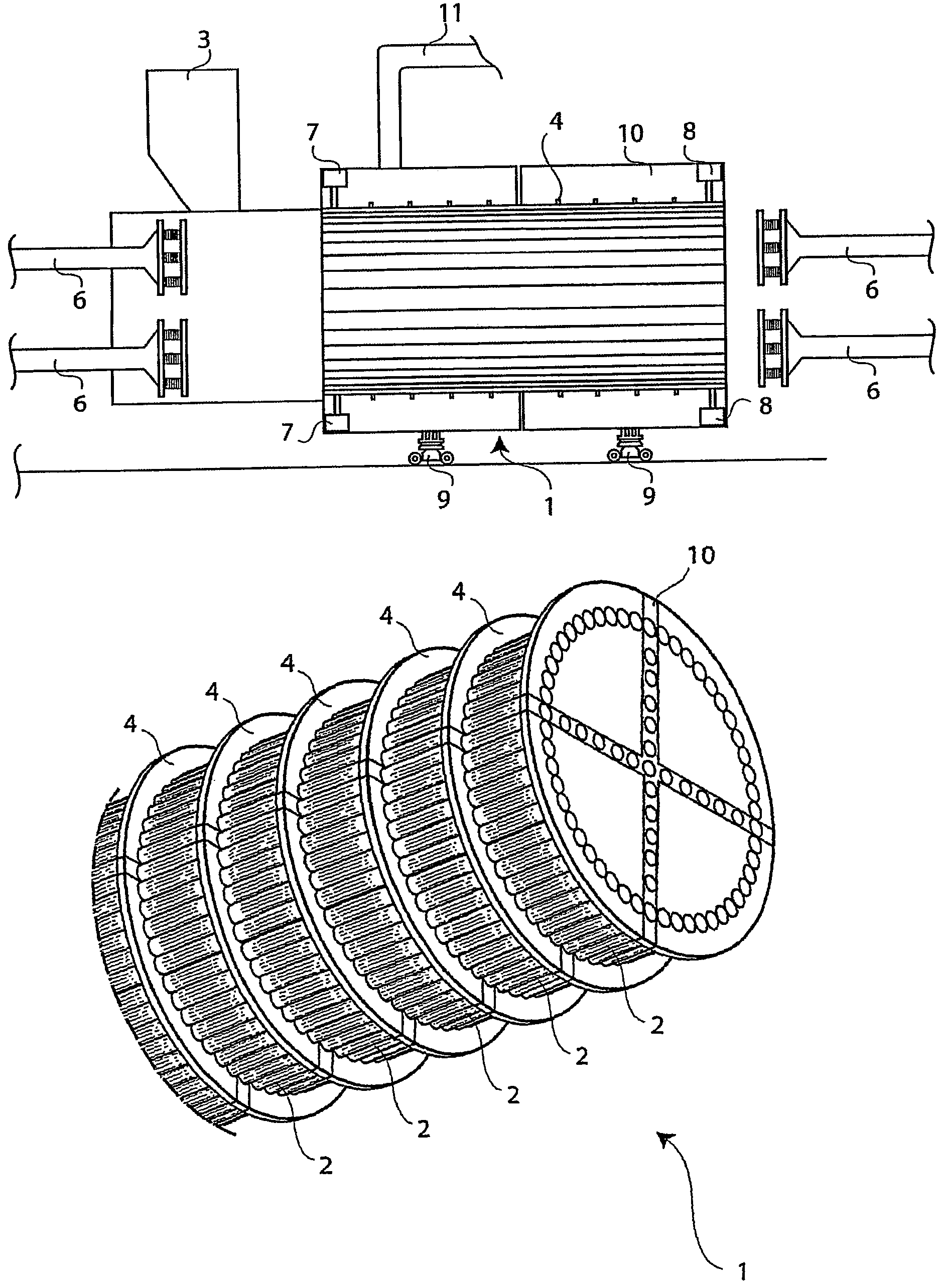
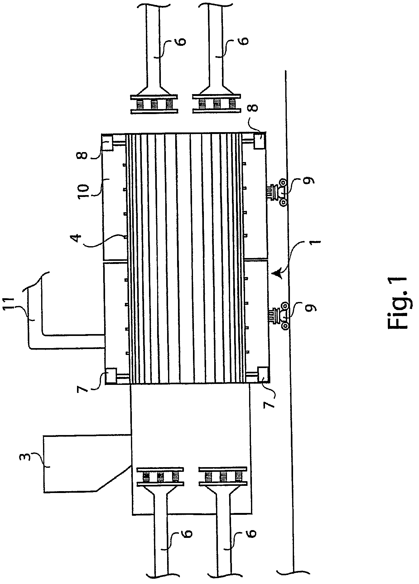
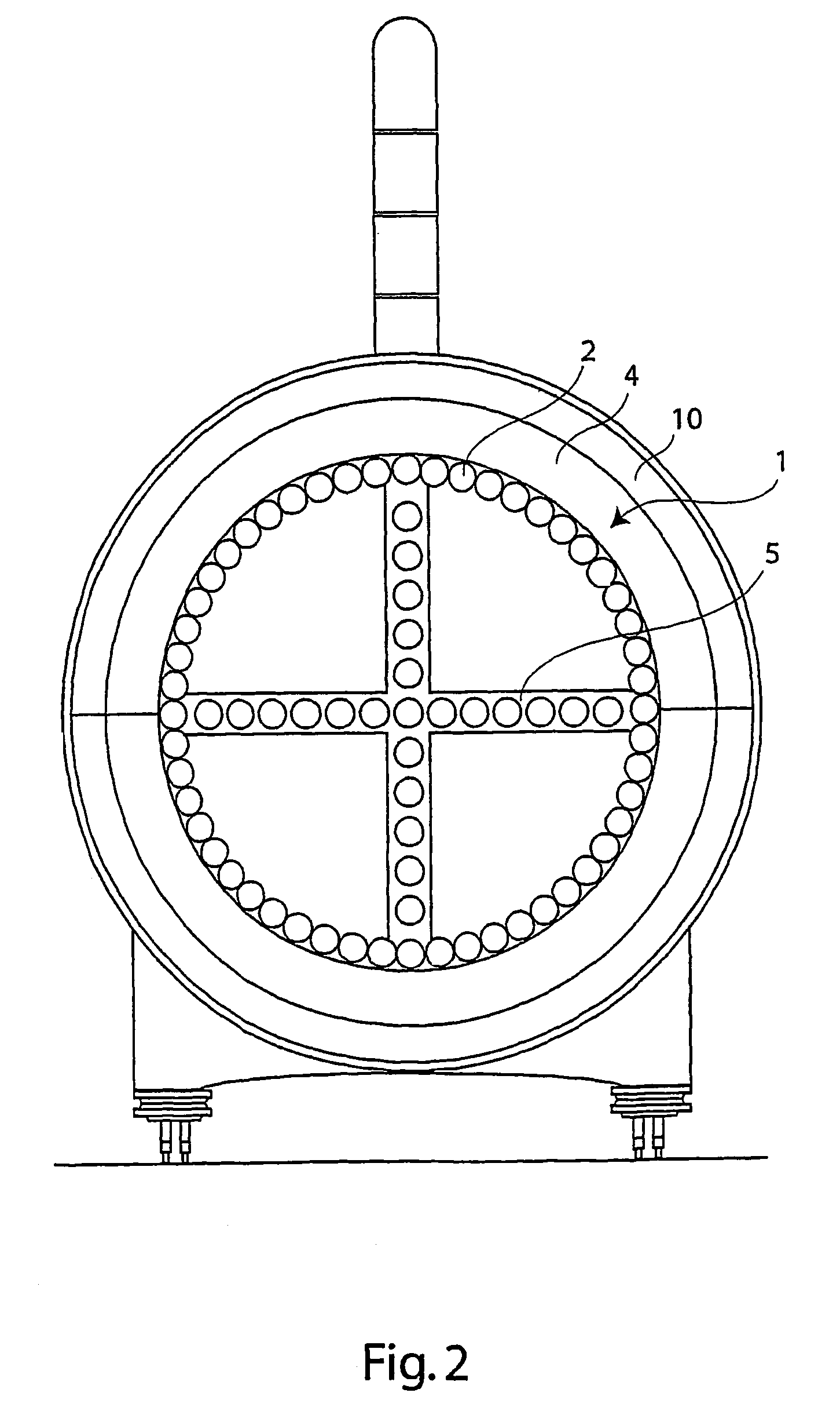
[0062]Making reference to the figures, it can be observed the main body of the drying—compacting apparatus of the invention comprising a cylindrical body 1, made up of an assembly of tubes 2 coursed by a thermal carrier fluid, said tubes 2 being positioned according to the generatrixes of the cylinder. Thus, within the tubes 2 a cylindrical space is realised, said space being divided into four equivalent sections by further tubes, coursed by the thermal carrier fluid, said further tubes being arranged according to a cross position. Wastes to be compacted and dried are discharged from above into the apparatus, within a loading chamber close to one of the basis of the cylindrical body, by a hopper 3. By the heat exchanged among the tubes, apparatus warms the discharged wastes, acting as an oven.

[0063]Furthermore, in view of the good features of the tube to act as beams, they are dimensioned and constrained in such a way that the cylindrical shaped lateral body acts also as bearing str...


PUM

PropertyMeasurementUnit
humidityaaaaaaaaaa
pressureaaaaaaaaaa
lengthaaaaaaaaaa

Abstract

A cage drying—compacting apparatus for wastes, includes a cylindrical shape and at least a pair of pressure plates, the cylindrical body having heating longitudinal tubes, coursed by a thermal carrier fluid, provided along the generatrixes of the cylinder and spaced from each other to realize longitudinal slots for outlet of vapour but not for outlet of material, coupled by constraint hinge elements, positioned at a given distance between centres, and the pressure plates being placed opposed each other, operating as movable basis of the body and acting as pistons. Heat sources are, provided inside the apparatus, all along its length, the sources include at least a tube coursed by thermal carrier fluid, an inlet for the material to be treated, and elements for collecting the material.

Description

BACKGROUND OF THE INVENTION[0001]The present invention relates to a double flow cage compactor dryer apparatus and method of compacting and drying wastes.[0002]The invention is included in the field of the apparatuses for treatment of industrial wastes, litter, or similar materials.[0003]Disposal of urban solid wastes is an always more felt problem in the modern life. Solutions presently used provide the placement of the wastes in a dump, or, as alternative, the incineration.[0004]Both these solutions have environmental drawbacks. In fact, most dumps quickly reach a saturation level and it is always more difficult to find new areas without protests of the inhabitants of the surrounding zones, worried about the air pollution due to the exhalation of wastes.[0005]Instead, incinerators, even the most technologically advanced for the thermo-valorisation can produce power with efficiency close to 20%, let in the air large amounts of carbon dioxide for each ton of burned waste, beside hav...

Claims


Application Information

Patent Timeline
Patent Type & Authority Patents(United States)
IPC IPC(8): F26B21/06B30B9/06B30B9/26F26B7/00F26B23/10
CPCB30B9/06B30B9/067B30B9/267F26B7/00F26B23/10F26B2200/04
Inventor LA GIOIA, ANTONIO
Owner LA GIOIA ANTONIO
Why Eureka
Try Eureka