Monitoring of a reservoir

a technology for monitoring and reservoirs, applied in the field of monitoring of reservoirs, can solve problems such as the risk of damage to flowlines and umbilicals that may occur

Inactive Publication Date: 2007-09-25
FMC KONGSBERG SUS
View PDF9 Cites 20 Cited by
  • Summary
  • Abstract
  • Description
  • Claims
  • Application Information

AI Technical Summary

Benefits of technology

[0017]The monitoring unit advantageously comprises a storage unit, thus enabling the information acquired to be stored until a suitable opportunity for transmitting data.

Problems solved by technology

One of the main reasons for this is the risk of damage to flowlines and umbilicals that may occur due to other activity in the vicinity, particularly drilling of adjacent wells.

Method used


Image

  • Monitoring of a reservoir
  • Monitoring of a reservoir

Examples


Embodiment Construction

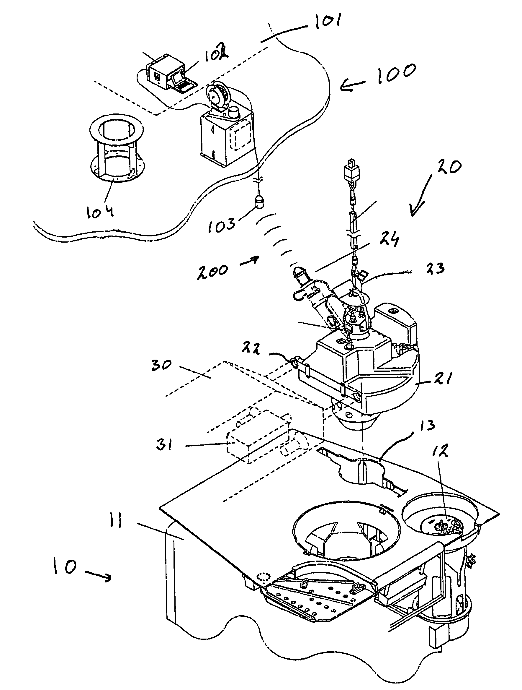
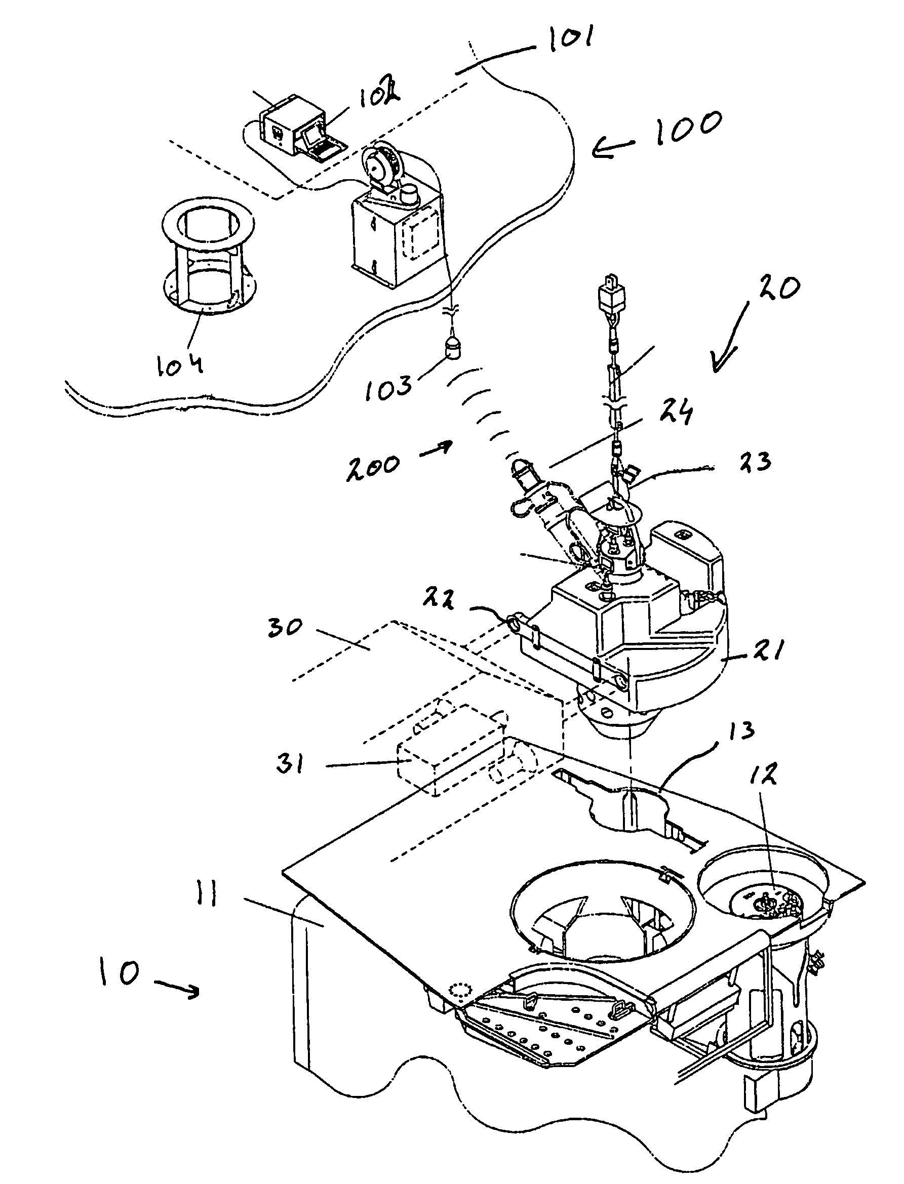
[0019]As illustrated in the drawing, the present invention is shown in conjunction with a well, which is generally indicated by 10, that is located on the seabed. The well extends downwardly into the seabed to a hydrocarbon-bearing formation and is completed in the normal manner. The well comprises a wellhead Christmas tree 11 which is equipped with valves (not shown) for control of the production and additional devices which are commonly known to a person skilled in the art. A control module 12 is mounted on the Christmas tree 11 and includes pilot valves for controlling hydraulic fluid to the valves in the Christmas tree, valves for injection of chemical treatment fluids, and control and monitoring systems for the well. In addition, a number of sensors (not shown) which are connected to the control module 12 are mounted in the well. The Christmas tree further includes a receiving device 13 which includes suitable mechanical and electrical connectors, the purposes of which will be ...


PUM


Abstract

A system is described for monitoring a subsea formation, which is under development. Instruments located in a completed but unconnected well are employed for providing information by a provisional monitoring unit being lowered downhole and connected to the well. Changes in the reservoir as a result of operations in other adjacent wells are intercepted by the instruments in the well and transmitted via an acoustic link to the surface.

Description

BACKGROUND OF THE INVENTION[0001]The invention relates to a system for monitoring a subsea oil or gas reservoir by means of measuring instruments located in a completed well.[0002]In exploring for oil or gas, particularly at great depths, it is desirable to know as much as possible about the hydrocarbon-bearing formation. In the initial phase of exploring for oil and gas this is done by means of seismic surveys, which provide an “image” of the formation. By analysing these images, geologists can then see whether there are oil and / or gas-bearing formations under the ground. However, it will not be possible to obtain a certain indication until wells have been drilled down to the reservoir.[0003]During drilling further information can be obtained about the formation (MWD=Measurement While Drilling). Measurements are carried out, for example, of pressure, temperature, resistivity and gamma waves. Another method normally employed for obtaining information about the reservoir is to take c...

Claims


Application Information

Patent Timeline
Patent Type & Authority Patents(United States)
IPC IPC(8): E21B29/12E21B47/00E21B47/12E21B47/14
CPCE21B47/0001E21B47/124E21B47/14E21B47/001E21B47/26E21B47/12G01V1/42
Inventor JOHANSEN, JOHN A.SIVERTSEN, MORTEN
Owner FMC KONGSBERG SUS
Why Eureka
Try Eureka