Method of manufacturing abrasive cutting string

a manufacturing method and cutting string technology, applied in the field of manufacturing abrasive cutting string, can solve the problems of viscous periphery of the string in which abrasive particles are embedded, and achieve the effects of improving the cutting string, enhancing the cutting efficacy of the cutting string, and simple and inexpensive methods

Inactive Publication Date: 2008-06-19
HOLT DAVID S
View PDF22 Cites 19 Cited by
  • Summary
  • Abstract
  • Description
  • Claims
  • Application Information

AI Technical Summary

Benefits of technology

[0008]Accordingly, it is an advantage of the invention described herein to provide an improved cutting string with an abrasive surface for cutting grass, weeds, brush and the like in combination with a rotary string trimmer.
[0009]It is a yet another advantage of the invention to provide a simple and inexpensive method for making such an improved cutting string.
[0010]Additional advantages of the invention will become apparent from an examination of the drawings and the ensuing description.SUMMARY OF THE INVENTION
[0011]The invention comprises a method of manufacturing cutting string for cutting grass, weeds, brush and the like when used in combination with motorized rotary head cultivation implements. Some variants of the cutting string may be used as the cutting line for string or wire saws as well. The preferred cutting string is composed of a plastomeric material and the manufacturing process fastens abrasives in plastomeric materials coated on the periphery of the string. The abrasives are applied to the cutting string after the cutting string is coated with a solution of a solvent and the plastomeric material comprising the string. This results in a viscous periphery of the string in which abrasive particles are embedded. Upon curing of the plastomeric material as by evaporation of solvent, the abrasives are set about the periphery of the string in the plastomeric material comprising the cutting string.
[0012]The method comprises the steps of forming a plastomeric cutting string, which is usually extruded in the same way as conventional cutting strings in this field from a plastomeric material, typically polyamide. The cutting string may have various profiles, the simplest shape being a circular cross-section but numerous alternative profiles have been proposed for cutting string such as disclosed in Skinner, Des. 376,739, Des. 379,052, Des. 379,418 and Des. 379,419; Fogle, U.S. Pat. No. 6,434,837 and Morabit, U.S. Pat. No. 5,996,233 with various jagged profiles. In a preferred method the cutting string is then passed through a solution of about 10 to 20 percent weight by volume of a solution of plastomeric string material. This results in the string having a viscous periphery of plastomeric material to which an abrasive coating is applied. The abrasive particles are typically inorganic particles such as silica, glass, fine sand, emery, marble, and coarse garnet. A variety of metallic particles such as carborundum, zinc, iron, and aluminum, especially in the form of powdered oxides of appropriate particle size may also be suitable abrasive coatings. In addition, particles of synthetic materials such as rigid plastics and combinations of two or more of the previously mentioned substances may also be advantageous.
[0013]The addition of abrasive particles enhances the cutting efficacy of the cutting strings by providing not only the impacting force of the string but also providing a sawing effect. The combination of the abrasive sawing effect in combination with the impact of the cutting line due to the rotational velocity significantly improves the cutting capability of the line, especially in connection with the heavier vegetation that cannot be severed by impacting force alone. As an added benefit, the nature of the abrasive particles may also improve the thermal characteristics of the cutting line and reduce any tendency of the cutting line to stick due to approaching melting point of the plastomeric material. In addition, with the appropriate abrasive coatings it becomes possible to rely upon the cutting or sawing effect of the abrasives to a much greater degree than the impacting effect of the rotational velocity imparted by the rotating head of the implement. In this case, the rotational speed of the head may be significantly reduced to perhaps several hundred rpm rather than several thousand rpm facilitating the use of less powerful motors and reducing the noise generated by the rotary head cultivation implement employed.

Problems solved by technology

This results in a viscous periphery of the string in which abrasive particles are embedded.

Method used


Image

  • Method of manufacturing abrasive cutting string
  • Method of manufacturing abrasive cutting string
  • Method of manufacturing abrasive cutting string

Examples


Embodiment Construction

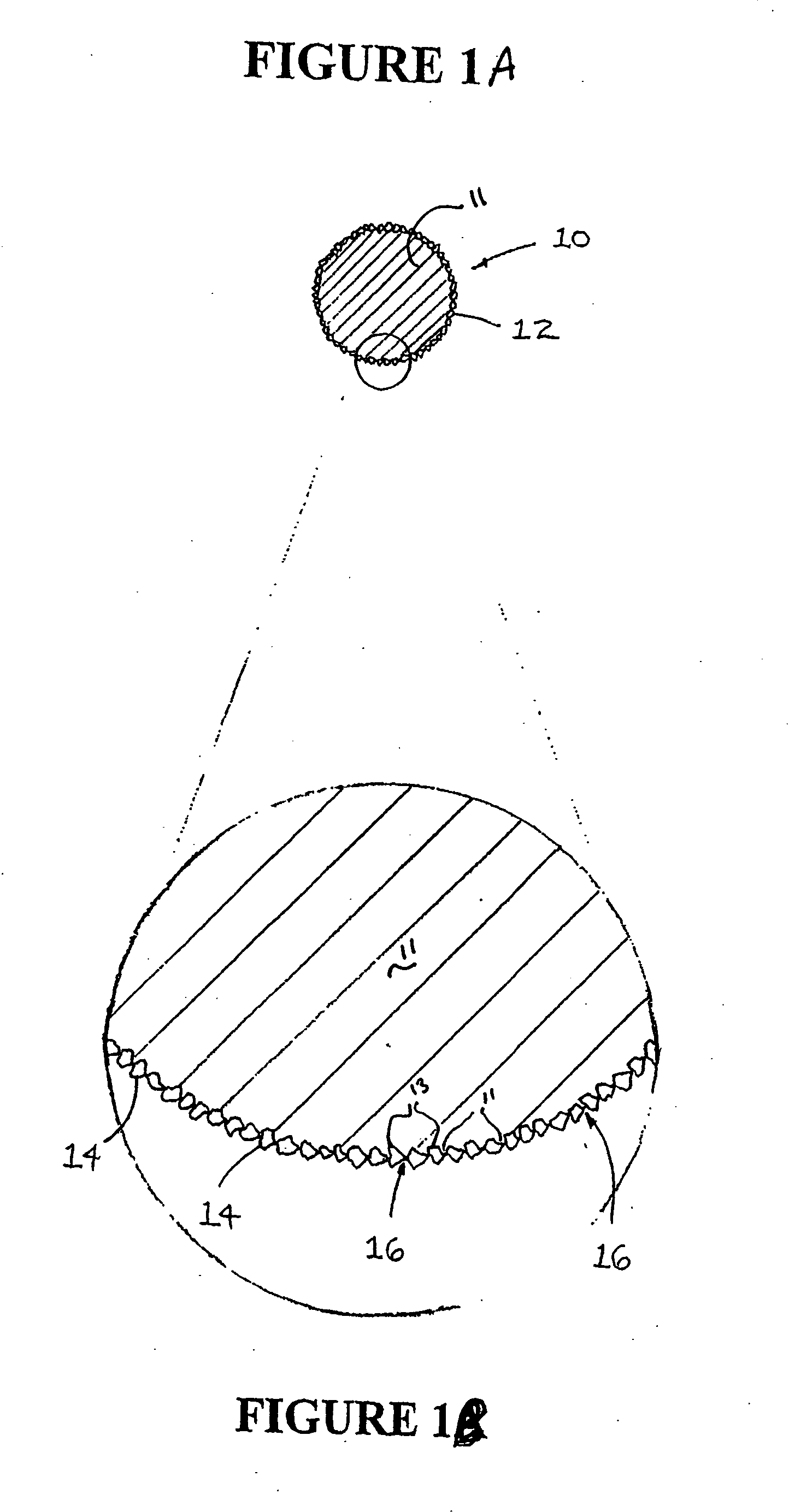
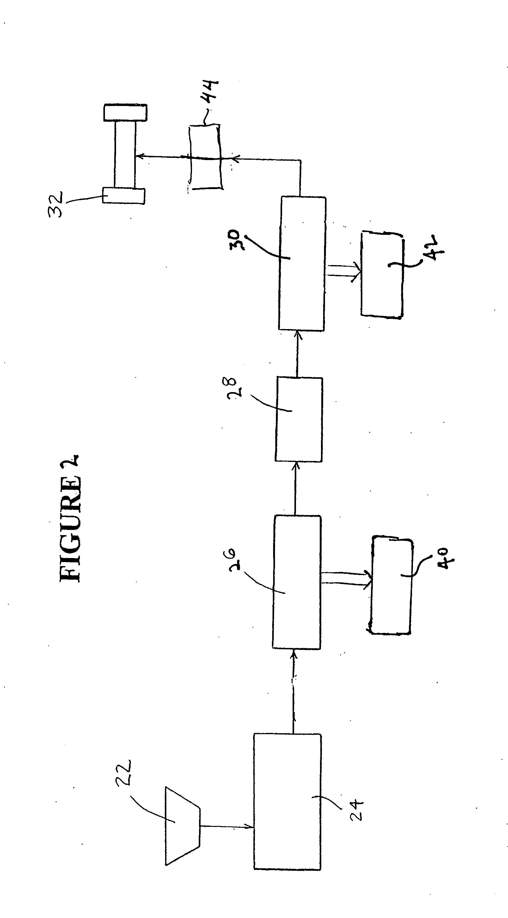
[0018]Referring now to the drawings, a cutting string 10 and a preferred method for making the cutting string of the invention are illustrated by FIGS. 1 through 2. As shown in FIG. 1A, a preferred cutting string is designated generally by reference numeral 10. The cutting string 10 is composed of a plastomeric material 11 such as Nylon 6 or Nylon 66 that is extruded to have a substantially circular cross-sectional shape. It is contemplated within the scope of the invention, however, that cutting string 10 may be composed of any suitable material that may be formed into a string-like configuration. Further, it is contemplated within the scope of the invention that cutting string 10 may be formed to have any suitable cross-sectional shape such as oval, crescent, semi-circular, triangular, square, rectangular, pentagonal, hexagonal, octagonal or any other polygonal shape. It is further contemplated within the scope of the invention that cutting string 10 may be produced by a process o...


PUM

PropertyMeasurementUnit
temperatureaaaaaaaaaa
diameteraaaaaaaaaa

Abstract

A method of producing an abrasive cutting string provides for coating a plastomeric string with a solution of a solvent and the plastomeric material of the string, applying an abrasive and removing the solvent to thereby provide a cutting string with excellent abrasive bind and string coverage, that can be manufactured at high speeds.

Description

FIELD OF THE INVENTION[0001]This invention relates generally to an improved method of manufacturing abrasive cutting string commonly used as cutting string for cutting grass, weeds, brush and the like in combination with a rotary string trimmer.BACKGROUND OF THE INVENTION[0002]It is known to use extruded thermoplastic string such as of Nylon to cut grass, weeds, brush and the like in combination with a rotary string trimmer. Conventional thermoplastic strings, however, suffer from several disadvantages. For example, conventional strings have a substantially smooth exterior surface. More particularly, the exterior surface of conventional strings is devoid of any abrasive or aggregate materials which produce cutting surfaces. Instead, conventional strings rely on the rotational velocity and impacting force of the string to cut weeds, grass, brush and the like. This, however, is an inefficient way to cut grass, weeds and particularly vegetation that cannot be felled with impacting forc...

Claims


Application Information

Patent Timeline
Patent Type & Authority Applications(United States)
IPC IPC(8): B24D18/00
CPCB24D11/001A01D34/4168
Inventor BHATIA, RAJEEV
Owner HOLT DAVID S
Why Eureka
Try Eureka