Wiring harness, connector, and method of assembling the wiring harness

a technology of wiring harnesses and connectors, which is applied in the direction of contact members penetrating/cutting insulation/cable strands, electrical equipment, and unstripped conductor connection devices, etc. it can solve the problems of shortened tooling life, increased frequency of changing tooling, and reduced tooling mechanical strength, so as to improve the mechanical strength of tooling and extend the working life of tooling. , the effect of reducing the size of the tooling

Active Publication Date: 2007-09-25
YAZAKI CORP
View PDF7 Cites 10 Cited by
  • Summary
  • Abstract
  • Description
  • Claims
  • Application Information

AI Technical Summary

Benefits of technology

[0026]According to the invention, since the flat circuit body is connected in one lump with the wire connecting portions of the plurality of terminals inserted in the connector housing, required hours for connecting the flat circuit body to the wire connecting portion of the terminals, that is assembling the wiring harness, can be extremely shortened.
[0027]Since the flat circuit body is connected in one lump with the wire connecting portions of the plurality of terminals, size of the tooling used for connecting the flat circuit body to the wire connecting portions of the terminals can be increased similarly as that of combining the plurality of terminals. Thereby, the mechanical strength of the tooling can be improved and the working life of the tooling can be extended. Therefore, frequency of changing the tooling can be reduced, and cost for assembling the wiring harness can be reduced.
[0028]Since the connector housing is further provided with a cutout exposing the wire connecting portions of the terminals inserted in the connector housing, by piling the flat circuit body on the wire connecting portions of the terminals and pressing the flat circuit body toward the wire connecting portions, the flat circuit body can be connected with the wire connecting portions. Therefore, without removing the insulator between adjacent conductors at a front end of the flat circuit body, the flat circuit body can be connected with the terminals. Thereby, required hours for connecting the flat circuit body to the wire connecting portion of the terminals, that is assembling the wiring harness, can be extremely shortened.
[0029]According to the invention, since the flat circuit body is connected in one lump with the wire connecting portions of the plurality of terminals inserted in the connector housing, required hours for connecting the flat circuit body to the wire connecting portion of the terminals, that is assembling the wiring harness, can be extremely shortened.
[0030]Since the flat circuit body is connected in one lump with the wire connecting portions of the plurality of terminals, size of the tooling used for connecting the flat circuit body to the wire connecting portions of the terminals can be increased similarly as that of combining the plurality of terminals. Thereby, the mechanical strength of the tooling can be improved and the working life of the tooling can be extended. Therefore, frequency of changing the tooling can be reduced, and cost for assembling the wiring harness can be reduced.
[0031]Since the connector housing is further provided with a cutout exposing the wire connecting portions of the terminals inserted in the connector housing, by piling the flat circuit body on the wire connecting portions of the terminals and pressing the flat circuit body toward the wire connecting portions, the flat circuit body can be connected with the wire connecting portions. Therefore, without removing the insulator between adjacent conductors at a front end of the flat circuit body, the flat circuit body can be connected with the terminals. Thereby, required hours for connecting the flat circuit body to the wire connecting portion of the terminals, that is assembling the wiring harness, can be extremely shortened.

Problems solved by technology

Thereby, the tooling is miniaturized to reduce mechanical strength of the tooling, and a life of the tooling is shortened.
Therefore, frequency of changing the tooling increases, so that cost of connecting the terminal and the FFC, that is assembling the wiring harness, increased.

Method used


Image

  • Wiring harness, connector, and method of assembling the wiring harness
  • Wiring harness, connector, and method of assembling the wiring harness
  • Wiring harness, connector, and method of assembling the wiring harness

Examples


Embodiment Construction

[0051]A wiring harness, a connector and a method of assembling the wiring harness of each embodiment according to the present invention will be described with reference to FIGS. 1-10.

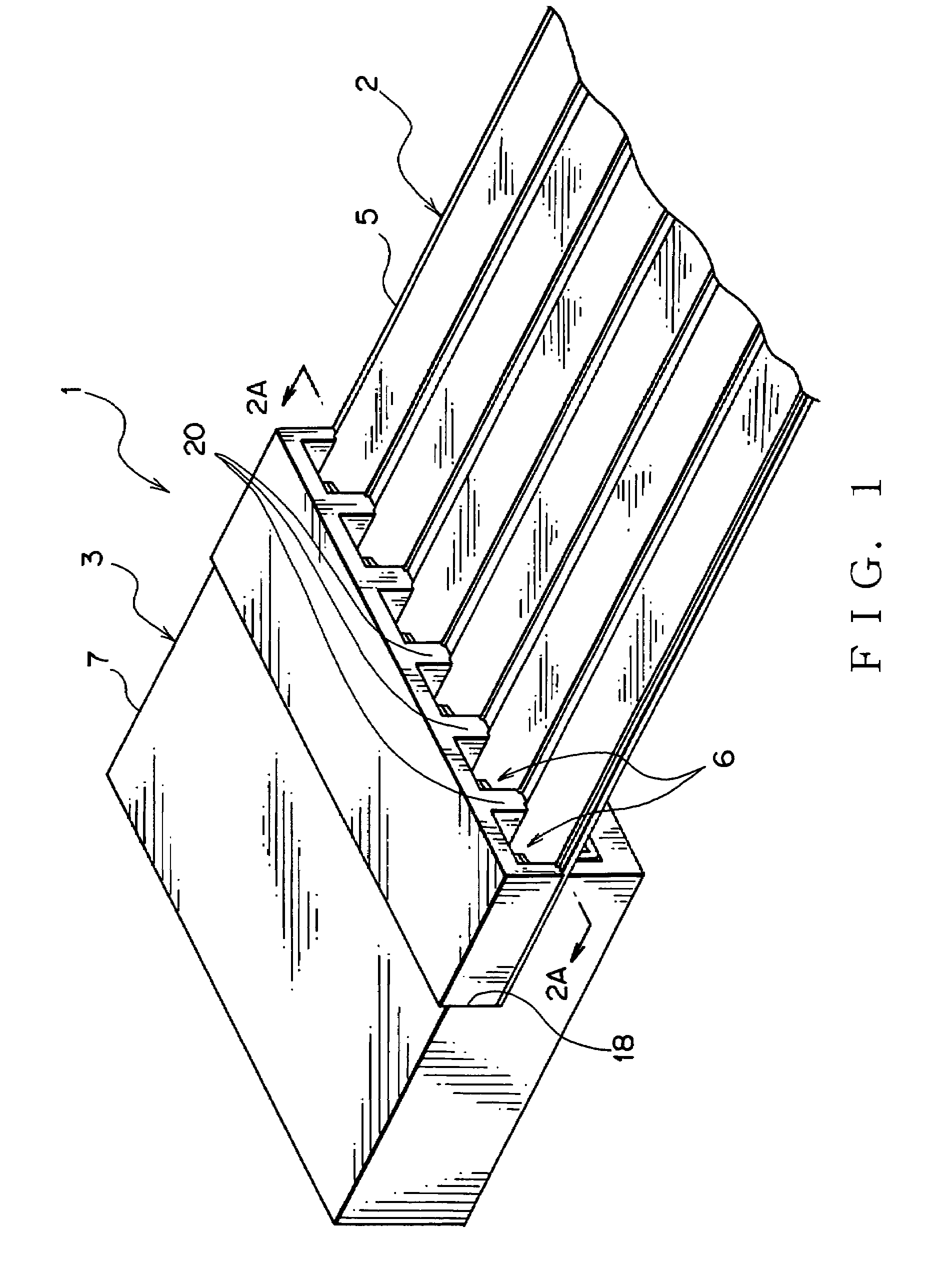
[0052]A wiring harness 1 includes an FFC 2 (Flexible Flat Cable) as a flat circuit body and a connector 3, as shown in FIG. 1.

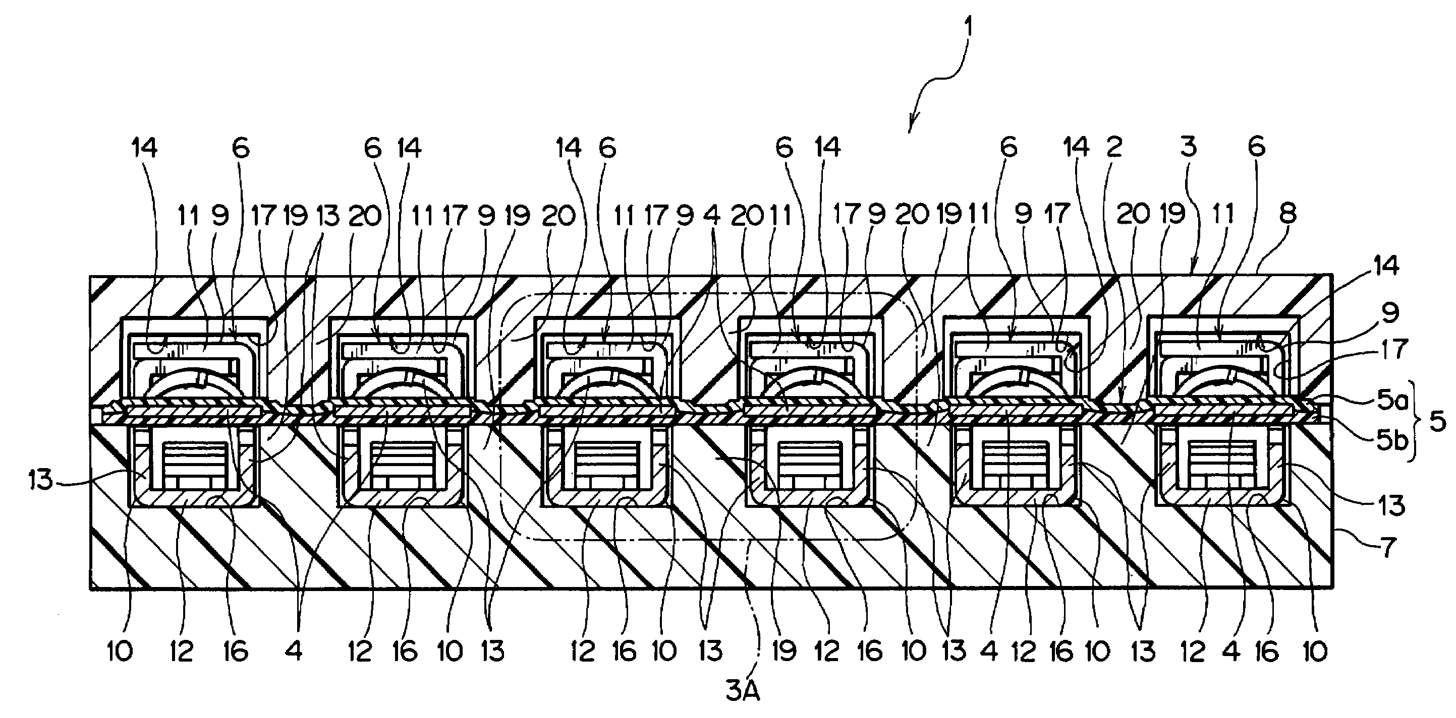
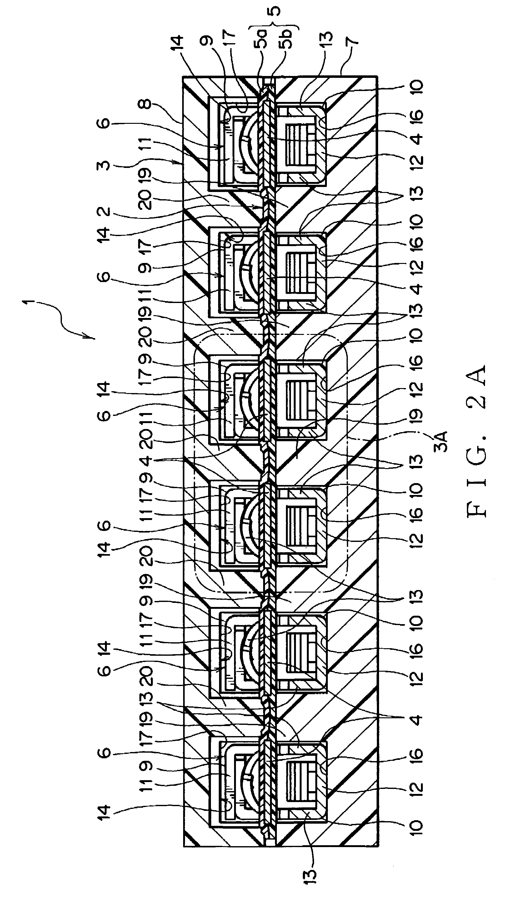
[0053]The FFC 3 has a plurality of conductors 4 and an insulator covering the conductors, as shown in FIGS. 2A, 3A.

[0054]The conductor 4 is made of electrically conductive metal. The conductor 4 includes at least copper or copper alloy. The conductor 4 is formed with rectangular cross-section. The conductor 4 extends linearly. The plurality of conductors 4 is arranged in parallel to each other.

[0055]An insulator 5 has a pair of insulation sheets 5a, 5b. The insulation sheets 5a, 5b are made of insulating synthetic resin and formed into band shape. The insulating sheets 5a, 5b are made of, for example, polyethyleneterephthalate; PET. The pair of insulating sheets 5a, 5b receives t...


PUM


Abstract

Providing a method of assembling a wiring harness and the wiring harness and a connector allowable to reduce required hours and a cost for assembling the wiring harness, the wiring harness includes a FFC and the connector. The FFC has a plurality of conductors and an insulator covering the conductors. The connector has piercing terminals, a connector housing and a cover. The piercing terminal has claws. A plurality of piercing terminals is received in the connector housing. The connector housing and the cover are provided with separating walls for clamping only the insulators of the FFC. By inserting the plurality of piercing terminals into the connector housing, making the claws pierce through the FFC, and bending the claws, the wiring harness is assembled.

Description

[0001]The priority application Number Japan Patent Application 2005-129216 upon which this patent application is based is hereby incorporated by reference.BACKGROUND OF THE INVENTION[0002]1. Field of the Invention[0003]This invention relates to a method of assembling a wiring harness having a flat circuit body, such as a FPC (Flexible Printed Circuit) and a FFC (Flexible Flat Cable), and the wiring harness and a connector to be connected with the flat circuit body.[0004]2. Description of the Related Art[0005]Various electronic apparatuses are installed in a car as a vehicle. In the car, a wiring harness is wired for transmitting electric power and control signals. The wiring harness includes a FCC as the flat circuit body and a connector.[0006]The flat circuit body has a conductor with a rectangular cross-section and a film-shape insulator for covering the conductor. A plurality of conductors is arranged in the flat circuit body. Each conductor extends linearly. The plurality of con...

Claims


Application Information

Patent Timeline
Patent Type & Authority Patents(United States)
IPC IPC(8): H01R4/24
CPCH01R12/68H01R43/01
Inventor KUMAKURA, HIDETO
Owner YAZAKI CORP
Why Eureka
Try Eureka