Vehicle exhaust system hose and coupling assembly

a technology for exhaust systems and hoses, applied in ventilation systems, heating types, stoves or ranges, etc., can solve the problems of external cables that can get caught on personnel or equipment, and external cables are also dangerous, and achieve good effects

Inactive Publication Date: 2007-09-25
FRINK ROBERT
View PDF29 Cites 13 Cited by
  • Summary
  • Abstract
  • Description
  • Claims
  • Application Information

AI Technical Summary

Benefits of technology

[0014]The present invention is an improved automatic detaching coupling for use, primarily, in emergency vehicle exhaust applications. The fire truck exhaust pipe is fitted with an Exhaust Pipe Adapter which forms the male portion of the coupling. The female portion of the coupling is a nozzle fitted with a snap ring. Said nozzle allows for the introduction of ambient air. The Exhaust Pipe Adapter, which is designed to be permanently disposed on the exhaust pipe, has a groove cut into its outer circumference. The groove accommodates the snap ring. Said snap ring is circular, but with a cut through the circle so it is not a continuous circle. This snap ring snaps on and off the groove with relative ease and provides good action. In other words there is a distinct signal (i.e. snap) whenever the snap ring snaps on or off the groove.

Problems solved by technology

The external cables are also dangerous as they can get caught on other equipment or personnel.
The prior art has external cables that can get caught on personnel or equipment.

Method used


Image

  • Vehicle exhaust system hose and coupling assembly
  • Vehicle exhaust system hose and coupling assembly
  • Vehicle exhaust system hose and coupling assembly

Examples


Embodiment Construction

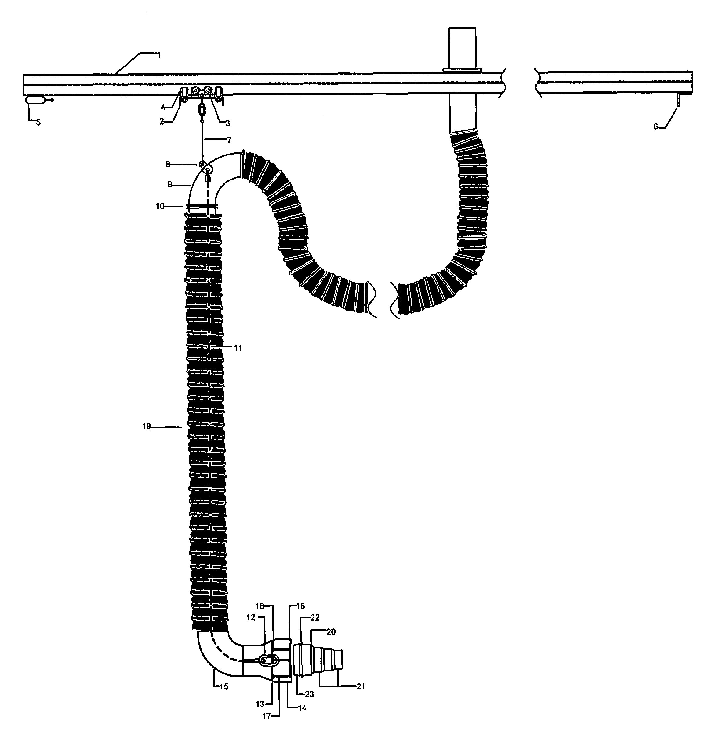
[0022]Referring specifically to FIGURE FIVE, a Track is suspended from a ceiling. A Trolley Plate 2 is fitted with four Thrust Load Wheels 3, two on each side of the Track 1, and four Radial Load Wheels 4, two on each side of the interior of the Track. The Trolley Plate 2 is oriented in the horizontal plane, however, said Trolley Plate 2 is bent downward in the front and back thereby providing a surface with a vertical orientation perpendicular to said Track 1. A Pneumatic Damper 5 is attached to the Track 1 such that the Pneumatic Damper 5 contacts the one vertical components of the Trolley Plate 2 when said Trolley Plate 2 approaches that end of the Track 1. The other end of the Track 1 could be equipped with another Pneumatic Damper 5 or just a Stop 6, depending on whether the fire station has one set of doors or two.

[0023]An Upper Static Cable 7 is attached to the Trolley Plate 2 and a Cable Bracket 8 having an outside eyelet and an inside eyelet. The Cable Bracket 8 is welded s...


PUM


Abstract

An improved de-coupling device for vehicle exhaust systems specifically emergency vehicle exhaust systems. In this application, flexible hoses are normally utilized as a conduit for exhaust fumes. This invention incorporates a tether inside the flexible hose thereby alleviating tension on the flexible hose. The weight of the nozzle elbow and the natural moment that is produced when a fire truck leaves the fire station with the nozzle on offers an ideal application for the snap ring assembly. The tether and the flexible hose are typically straight or near straight and when the fire truck leaves the station, tension is supplied by the cable, and when a sufficient moment is generated, the nozzle breaks free.

Description

BACKGROUND OF THE INVENTION[0001]1. Field of the Invention[0002]This invention relates to a vehicle exhaust hose, specifically, an exhaust hose which is connected to a vehicle tail pipe or exhaust pipe so that the vehicle can be idling indoors and then driven out of the building / garage. This invention is particularly well suited for fire trucks and other emergency vehicles. The device easily snaps on and, when the truck leaves, snaps off automatically.[0003]2. Description of Prior Art[0004]The Crane Patent (U.S. Pat. No. 1,112,681) involves a metal hose with a check valve and a fastening device for vehicle exhaust of stationary vehicles.[0005]The Imming Patent (U.S. Pat. No. 3,473,462) is a vehicle exhaust system with a fan. The placement of the exhaust hose is accomplished with winches and is designed for stationary vehicles.[0006]The Hohman Patent (U.S. Pat. No. 4,906,032) is a devise for fitting an exhaust hose onto a tailpipe using a spring pressing against the inside surface of...

Claims


Application Information

Patent Timeline
Patent Type & Authority Patents(United States)
IPC IPC(8): B08B15/00B60D1/58A47L5/00A47L9/00B08B5/00F16L9/14F16L35/00
CPCB08B15/002B08B15/005F16L35/005F01N2450/10
Inventor FRINK, ROBERT
Owner FRINK ROBERT
Why Eureka
Try Eureka