Pattern recognition apparatus using parallel operation

Active Publication Date: 2007-09-25
CANON KK
View PDF23 Cites 34 Cited by
  • Summary
  • Abstract
  • Description
  • Claims
  • Application Information

AI Technical Summary

Benefits of technology

[0013]It is object of the present invention to provide pattern recognition processing capable of efficiently performing recognition using a small-scale circuit for detecting (recognizing) a pattern of a predetermined category and size.
[0015]It is still another object of the present invention to provide pattern recognition processing capable of detecting an object in a highly reliable fashion even when the object to be detected is partially occluded by another object.

Problems solved by technology

When the degree of similarity in terms of a local part of an object model is evaluated, if a part of an object is hidden, there is a possibility that difficulty occurs in the evaluation of the degree of similarity.
However, in the technique disclosed in Japanese Patent Laid-Open No. 11-15945, when there are a plurality of categories in object models, it is not disclosed which local model should be employed and how matching results are consolidated.
Furthermore, when the overall likelihood of presence of a feature is determined using non-additive measures on the basis of the Dempster-Shafer technique, it is not necessarily ensured that the resultant overall likelihood indicates optimum estimation.
Another problem is that when the size of an object in an image to be recognized is different from that of object model, or when an image includes a plurality of objects with different sizes, the technique encounters difficulty.
However, this needs a large-scale circuit (large memory size) and the processing efficiency is low.
In the parallel processing apparatus disclosed in Japanese Patent Laid-Open No. 9-153021, if input data includes a plurality of objects with different sizes, it is difficult to properly divide the input data.
That is, when the type or size of an object is unknown, if an input signal is simply divided in a fixed manner, parallel processing for pattern recognition cannot be properly performed.
Therefore, depending on the size of an input image, a large number of elements are required in a low-level layer, and thus a large-scale circuit is needed.

Method used


Image

  • Pattern recognition apparatus using parallel operation
  • Pattern recognition apparatus using parallel operation
  • Pattern recognition apparatus using parallel operation

Examples


first embodiment

Brief Description of the General Construction and Respective Elements

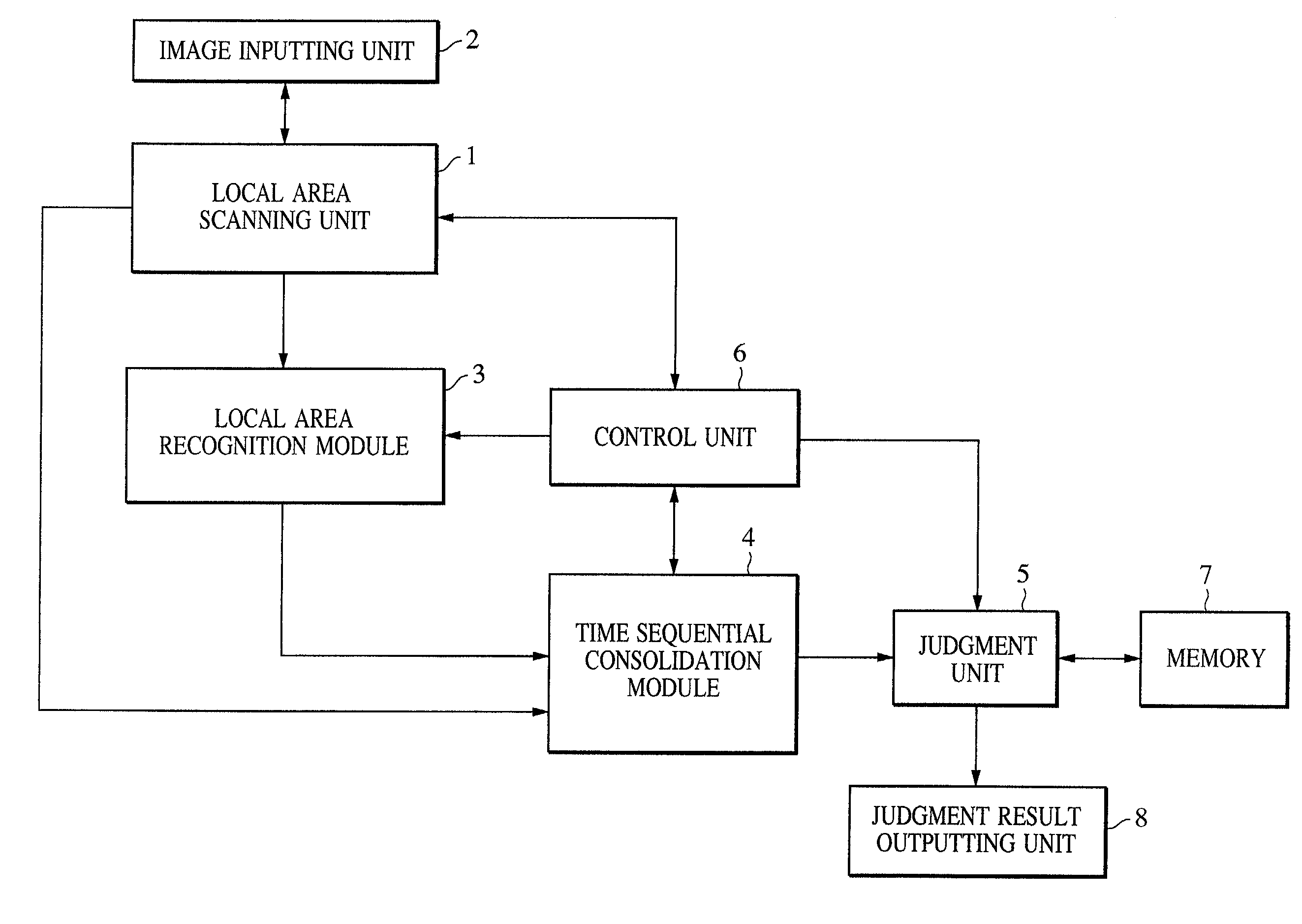
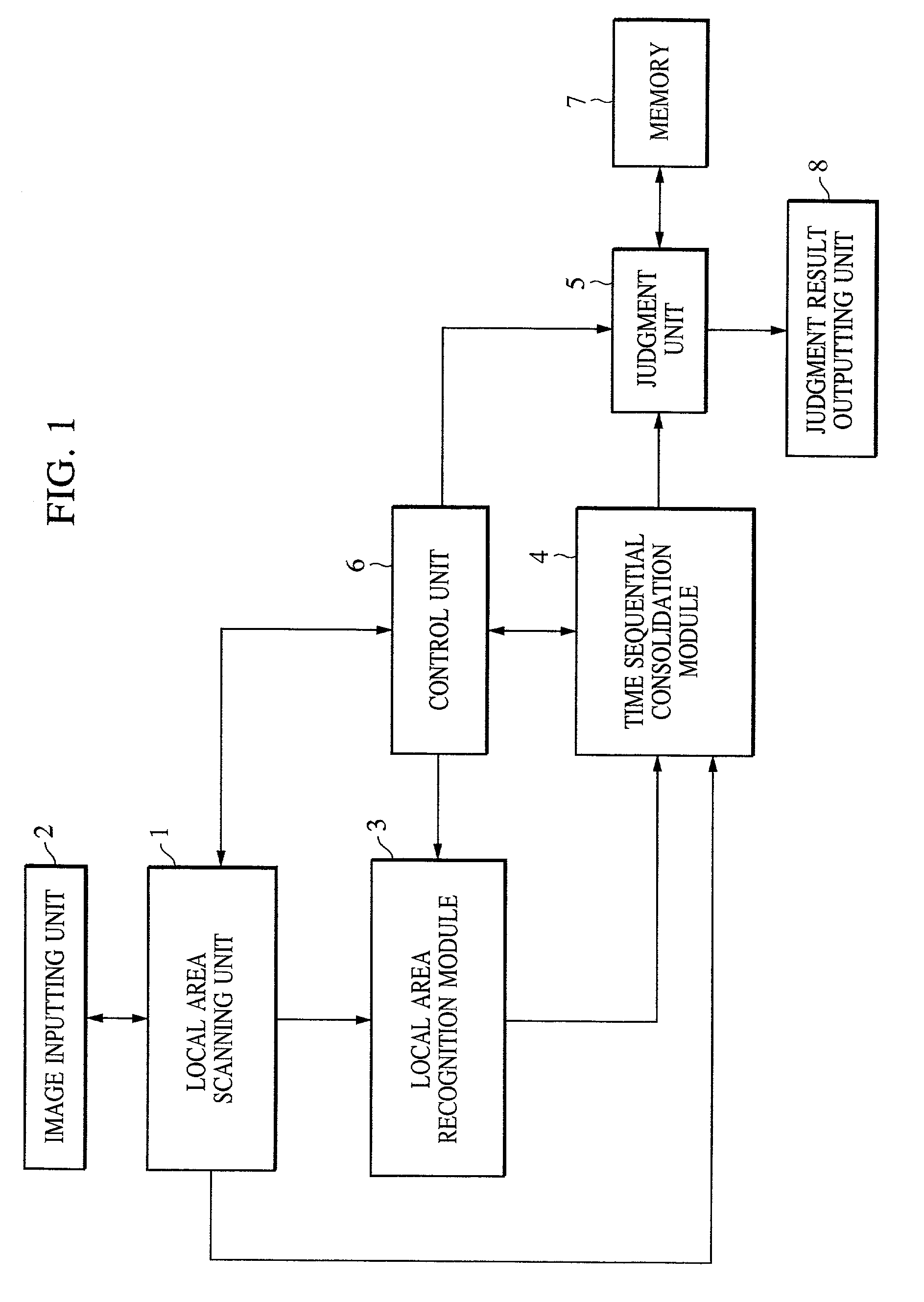
[0037]A first embodiment is described in detail below with reference to the accompanying drawings. FIG. 1 generally illustrates a pattern recognition apparatus according to the first embodiment. The pattern recognition apparatus includes a local area scanning unit 1, an image inputting unit 2, a local area recognition module 3, a time-sequential consolidation module 4, a judgment unit 5, and a control unit 6 for controlling the operations of the above units or modules. Functions of the respective units / modules are described below.

[0038]In accordance with a control signal supplied from the control unit 6, the local area scanning unit 1 defines, in the data input via the image inputting unit 2, a local area with a rectangular shape (block shape or another shape) having a size determined by the control unit 6, at a sampling point position which is changed one by one. In the block scanning process, it is desirable that...

second embodiment

[0091]In this second embodiment, the sampling point position scanned by the local area scanning unit 1 is changed in accordance with a predetermined procedure (raster scanning procedure), and the block size is fixed (based on the predetermined maximum size of an object to be detected). Thus, in the present embodiment, the controlling of the sampling point position during the process does not depend on the output from the local area recognition module 3. As in the previous embodiment, the local area recognition module 3 detects a middle-order or high-order pattern. The construction of the pattern recognition apparatus is similar to that according to the first embodiment.

[0092]Of course, high-order patterns to be detected should have a size smaller than the block size. Scanning is performed over the entire input data without changing the block size. As in the first embodiment, the local area recognition module 3 includes processing channels assigned to different object sizes to detect...

third embodiment

[0102]In this third embodiment, the size of the block-shaped local area defined by the scanning unit 1 is controlled by a block setting unit (not shown), and consolidation and recognition are performed by the local area recognition module 3, the time-sequential consolidation module 4, and the judgment unit 5. As in the first embodiment, the local area recognition module 3 includes a plurality of parallel processing channels corresponding to different scale levels. The block size may be updated according to one of two methods described below. In the first method, the control unit 6 determines the block size at each scanning position, and the local area recognition module 3 outputs data at each scanning position. In the second method, consolidation and recognition are performed by scanning the entire input data while fixing the block size. Thereafter, the block size is changed and consolidation and recognition are performed for the updated block size.

[0103]In the second method, in man...


PUM


Abstract

In a pattern recognition apparatus, a local area recognition module is constructed with operation elements having predetermined operation characteristics. Pattern data of a predetermined size in input data is acquired by time-sequentially performing inputting process at a plurality of times via a local area scanning unit, and information indicating the position of pattern data in the input data is output. The local area recognition module detects a feature of a predetermined middle-order or high-order category from the pattern data. A consolidation module time-sequentially consolidates outputs from the local area recognition module on the basis of the position information and the category of the feature thereby producing feature detection map information. A judgment unit outputs position information and category information of a high-order feature present in the input data, on the basis of the output from the time-sequential consolidation module.

Description

BACKGROUND OF THE INVENTION[0001]1. Field of the Invention[0002]The present invention relates to a pattern recognition apparatus using a parallel operation.[0003]2. Description of the Related Art[0004]Image / speech recognition techniques can be generally classified into two types. In one type, a recognition algorithm specialized for recognition of a particular type of image / voice is described in the form of computer software and executed sequentially. In the other type, recognition is performed using a dedicated parallel image processor (such as a SIMD or MIMD machine).[0005]One widely-used image recognition algorithm is to calculate a feature value indicating the degree of similarity between an image of an object and an object model. In this technique, model data of an object to be recognized is represented in the form of a template model, and recognition is performed by calculating the degree of similarity between an input image (or a feature vector thereof) and a template or by ca...

Claims


Application Information

Patent Timeline
IPC IPC(8): G06K9/00G06T7/00G06K9/66
CPCG06K9/00281G06K9/00986G06K9/4628G06V40/171G06V10/955G06V10/454
Inventor MATSUGU, MASAKAZU
Owner CANON KK
Why Eureka
Try Eureka