Method for fabricating an acoustical resonator on a substrate

a technology of acoustic resonance and substrate, which is applied in the manufacture/assembly of the diaphragm/electrostrictive device, transducer type, coating, etc., can solve the problems of high cost and size limitations of the components contained in the electronic device, and the fabrication of the membrane structure is very complex

Inactive Publication Date: 2007-10-02
AVAGO TECH INT SALES PTE LTD
View PDF22 Cites 153 Cited by
  • Summary
  • Abstract
  • Description
  • Claims
  • Application Information

AI Technical Summary

Problems solved by technology

Consumer electronics such as cellular telephones and miniature radios place severe limitations on both the size and cost of the components contained therein.
Unfortunately, the fabrication of these membrane structures is very complex.
The challenges in the manufacturing process for these types of structures include 1) depositing multiple films with severe constraints on smoothness; 2) being able to accurately measure and monitor the thickness of each layer (especially multiple layers; 3) manufacturing a high-volume, high throughput process that is amenable to multiple depositions in one process step.

Method used


Image

  • Method for fabricating an acoustical resonator on a substrate
  • Method for fabricating an acoustical resonator on a substrate
  • Method for fabricating an acoustical resonator on a substrate

Examples


Embodiment Construction

[0021]A manufacturing process for thin film bulk acoustic resonator (fbar) filters is described. In the following description, for the purposes of explanation, numerous specific details are set forth in order to provide a thorough understanding of the present invention. It will be apparent, however, to one skilled in the art that the present invention may be practiced without these specific details. In other instances, well-known structures and devices are shown in block diagram form in order to avoid unnecessarily obscuring the present invention.

[0022]General Processing Flow and Structure

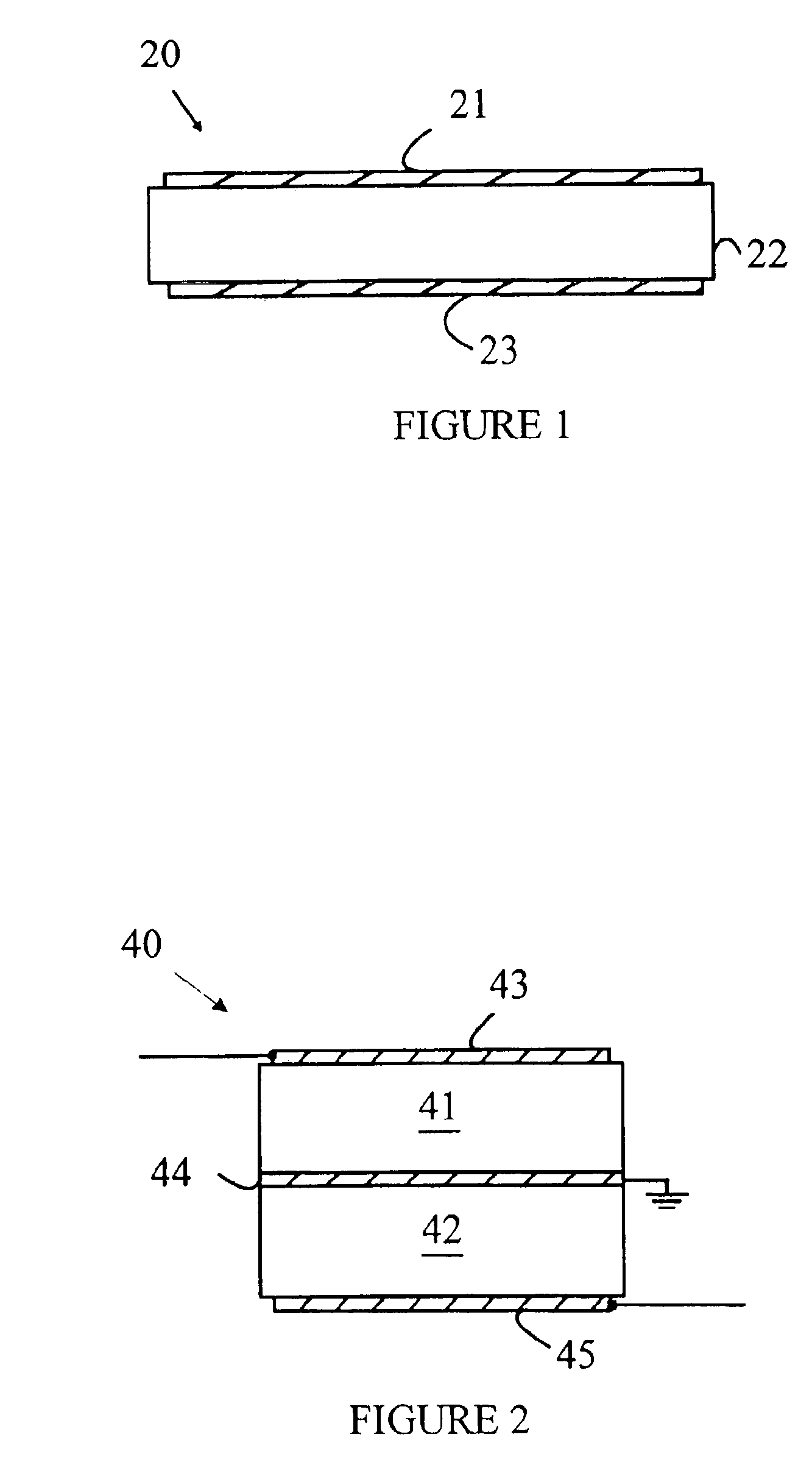
[0023]The present invention may be more easily understood with reference to FIGS. 1 and 2, which are cross-sectional views of an FBAR and an SBAR, respectively. Referring to FIG. 1, FBAR 20 includes bottom and top electrodes 23 and 21, respectively, which sandwich a portion of a sheet of piezoelectric (PZ) material 22. The preferred PZ material is aluminum nitride (AlN). The electrodes used in reso...


PUM

PropertyMeasurementUnit
diameteraaaaaaaaaa
thicknessaaaaaaaaaa
thicknessaaaaaaaaaa

Abstract

Method for fabricating an acoustical resonator on a substrate having a top surface. First, a depression in said top surface is generated. Next, the depression is filled with a sacrificial material. The filled depression has an upper surface level with said top surface of said substrate. Next, a first electrode is deposited on said upper surface. Then, a layer of piezoelectric material is deposited on said first electrode. A second electrode is deposited on the layer of piezoelectric material using a mass load lift-off process.

Description

FIELD OF THE INVENTION[0001]The present invention relates generally to acoustic resonators, and more particularly, to resonators that may be used as filters for electronic circuits and a method of manufacturing the same.BACKGROUND OF THE INVENTION[0002]The need to reduce the cost and size of electronic equipment has led to a continuing need for smaller filter elements. Consumer electronics such as cellular telephones and miniature radios place severe limitations on both the size and cost of the components contained therein. Many such devices utilize filters that must be tuned to precise frequencies. Hence, there has been a continuing effort to provide inexpensive, compact filter units.[0003]One class of filter element that has the potential for meeting these needs is constructed from acoustic resonators. These devices use bulk longitudinal acoustic waves in thin film piezoelectric (PZ) material. In one simple configuration, a layer of PZ material is sandwiched between two metal elec...

Claims


Application Information

Patent Timeline
Patent Type & Authority Patents(United States)
IPC IPC(8): H04R17/00B05D5/12H01L41/00H03H3/02H03H3/04H03H9/02H03H9/58
CPCH03H3/02H03H3/04H03H9/02149H03H2003/0471Y10T29/49002Y10T29/49156Y10T29/49155Y10T29/49005Y10T29/42
Inventor RUBY, RICHARD C.LARSON, JOHN D.BRADLEY, PAUL D.
Owner AVAGO TECH INT SALES PTE LTD
Why Eureka
Try Eureka