
Process for producing rotationally symmetrical components

Inactive Publication Date: 2007-10-02
MUHR UND BENNDER KG
View PDF13 Cites 7 Cited by
  • Summary
  • Abstract
  • Description
  • Claims
  • Application Information

AI Technical Summary

Benefits of technology

[0014]Therefore, an object of the invention is to devise a process for producing a rotationally symmetrical component from a pipe, which process can be carried out as simply and thus as economically as possible.
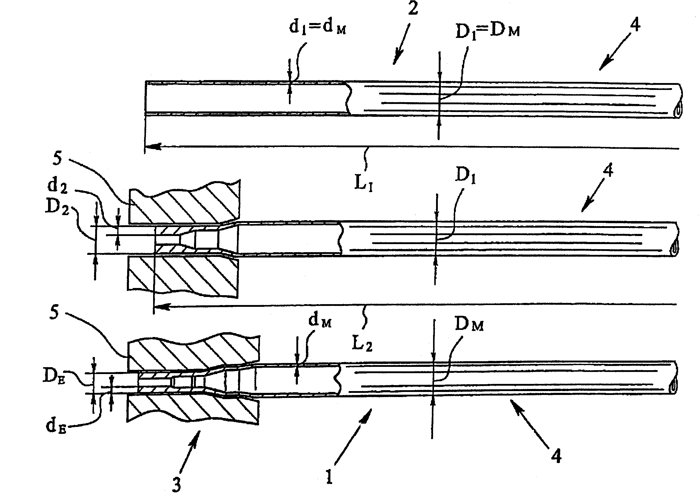
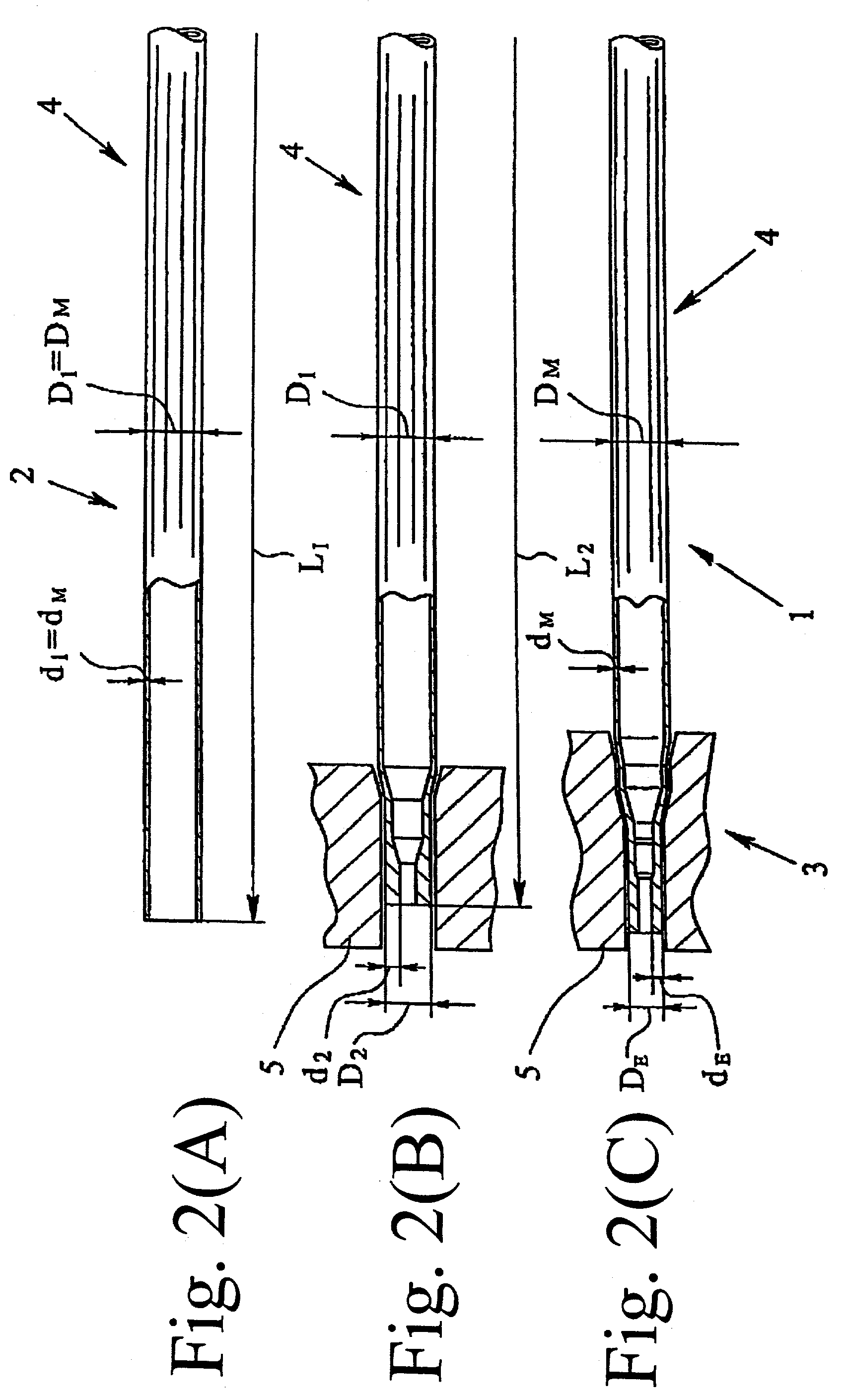
[0020]The process of the invention can be carried out more easily and thus more economically by using a pipe with a wall thickness which corresponds to the smallest wall thickness of the finished component as the initial starting material. Within the framework of this invention, only the wall thickness of an area of the component with a certain length is ever considered. If, for example, the edge of the component has a short shoulder which has a small wall thickness, this should not be understood as the smallest wall thickness of the component. Generally, the component will have its smallest wall thickness roughly in the middle area, however, the area of the smallest wall thickness need not be exactly in the middle of the component. In the process of the invention, the step of sinking of an area, especially the middle area of the pipe, which is generally necessary in the prior art, is eliminated. If the shaft to be produced from the pipe is to be the drive shaft of a motor vehicle, only the two end areas need be worked, but not the middle area. The material volume necessary for producing an end area with a large wall thickness, for which in the prior art a pipe with a greater wall thickness than the initial material is necessary, is made available in the production of the rotationally symmetrical component according to the process of the invention by axial upsetting of the heated area of the pipe.
[0021]It is particularly advantageous if a welded pipe, which has not been redrawn, is used as the pipe. In this way, as stated above, the production costs for the initial material, i.e. the pipe, can be significantly reduced. The process of the invention can be advantageously developed by carrying out axial upsetting and radial forging of the heated area of the pipe in a clamp, preferably in one step. When the pipe need not be re-clamped from one machine to another in the individual working steps, the production times are shorter for the rotationally symmetrical component; this likewise benefits production costs.
[0025]In the process according to the second embodiment of the invention, the production costs are reduced by using as the initial material a pipe which is simply welded, but which has not been redrawn. The material volume necessary to achieve an edge area of the pipe with a relatively large wall thickness is made available in this process by bending the pipe from sheet metal or steel strip with great thickness. Advantageously, in the process according to this second embodiment of the invention the wall thickness of the pipe corresponds to the smallest wall thickness of the finished component.

Problems solved by technology

When the pipe need not be re-clamped from one machine to another in the individual working steps, the production times are shorter for the rotationally symmetrical component; this likewise benefits production costs.

Method used


Image

  • Process for producing rotationally symmetrical components
  • Process for producing rotationally symmetrical components
  • Process for producing rotationally symmetrical components

Examples


Embodiment Construction

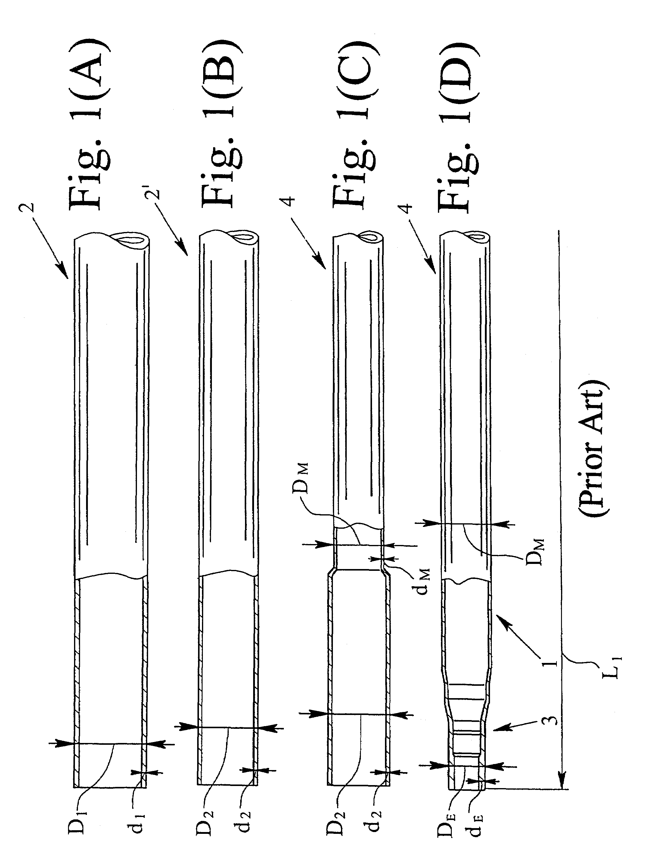
[0030]FIGS. 1A-1D schematically show the production sequence in the manufacture of a shaft 1 with an outside diameter D which varies over the entire length and a varying wall thickness d according to the process known from the prior art, proceeding from a pipe 2. Of the four production steps shown overall, the first two production steps (FIGS. 1A and 1B) relate to the production of the pipe 2, while the last two production steps (FIGS. 1C and 1D) relate to production of the shaft 1 from the pipe 2.

[0031]FIG. 1A shows a simply welded pipe 2 with an outside diameter D1 and a wall thickness d1. The wall thickness d1 corresponds to the thickness of the sheet metal or steel strip from which the pipe 2 has been bent. FIG. 1B shows the pipe 2′ after it has been drawn through a drawing die or drawing ring. By drawing the pipe 2, it has an outside diameter D21 and a wall thickness d21. This pipe 2′ is dimensioned such that from the pipe a shaft 1 with an end area 3 with the desired outside d...


PUM

PropertyMeasurementUnit
Thicknessaaaaaaaaaa
Diameteraaaaaaaaaa

Abstract

A process for producing a hollow monoblock shaft from a pipe, the pipe initially having a constant diameter and a constant wall thickness, and the monoblock component including at least one area of its length being of a smaller outside diameter and a greater wall thickness than the constant diameter and constant wall thickness of the pipe. The process can be carried out simply and economically by the following process steps:selecting a pipe with a wall thickness which corresponds to the smallest wall thickness of the finished component,partial heating of at least one area of the pipe,axial upsetting the heated area of the pipe andradial forging the heated area of the pipe.

Description

BACKGROUND OF THE INVENTION[0001]1. Field of the Invention[0002]The invention relates to a process for producing rotationally symmetrical components from a pipe, especially hollow monoblock shafts, the pipe initially having a constant outside diameter and a constant wall thickness, and the rotationally symmetrical component having at least over one area of its entire length an outside diameter which deviates from the constant outside diameter, especially as a smaller outside diameter, and / or a wall thickness which deviates from the constant wall thickness, especially as a greater wall thickness. In addition, the invention relates to a rotationally symmetrical component.[0003]2. Description of Related Art[0004]Rotationally symmetrical components which have different outside diameters and different wall thicknesses over their entire length are used especially in motor vehicles as drive shafts, camshafts, intermediate shafts or gear shafts. Under the aspect of “weight reduction” which ...

Claims


Application Information

Patent Timeline
IPC IPC(8): B21J5/08B21D41/04B21C37/16B21K1/12B21K21/12
CPCB21C37/16B21K21/12B21K1/12Y10T29/49945
Inventor GINSBERG, JOCHENMUHR, THOMAS
Owner MUHR UND BENNDER KG
Learn More