Medical aspirator

a technology of aspirator and aspiration chamber, which is applied in the field of medical aspirators, can solve the problems of increasing restarting load, affecting the operation of the pump, and affecting the portability of the device, so as to improve the poor restarting of the electric pump, reduce the burden on the operator, and avoid congestion at the place of use.

Inactive Publication Date: 2007-10-02
NIPRO CORP
View PDF14 Cites 82 Cited by
  • Summary
  • Abstract
  • Description
  • Claims
  • Application Information

AI Technical Summary

Benefits of technology

[0016]Therefore, in order to solve the problem of inferior portability, the inventor concentrated his energy on providing a medical aspirator excellent in portability which can reliably and easily be restarted after an emergency stop and is hardly contaminated and is unlikely to cause infection, and which eliminates visual confirmation by an operator of clogging in an aspiration catheter or an aspiration tube to thereby reduce a burden on the operator and ensure safety of a patient and improvement of aspiration efficiency. As a consequence, the inventors have devised the present invention.

Problems solved by technology

However, these medical aspirators have a significant problem in that they are inferior in portability.
This is because startup energy loss of a mechanism for converting a rotational movement into a reciprocating movement is large.
However, in a case in which the pump is stopped, since a negative pressure in the shut-off pump chamber is maintained, a restarting load increases.
Thus, it is particularly hard to restart a diaphragm pump.
This problem is particularly conspicuous in portable or mobile medical instruments, medical instruments for surgical operations, or the like.
Thus, it is difficult to obtain a sufficient output overcoming a high load at the time of restart.
In addition, during progress of an operation, emergency stopping or restarting may be required.
Thus, reliability of restart is a significant issue involving life or death for a patient.
However, it takes a lot of time and labor to perform these manipulations during an operation requiring urgency.
In addition, since the coupling tube is connected to the aspiration port, which has a complicated shape, there is the likelihood of air leakage due to a connection failure or contamination of the aspirator via bloodstained gloves, which may result in spreading of a disease to other patients.
However, this monitoring work is a significant burden for the operator who is manipulating a catheter in a blood vessel for acute myocardial infarction which requires urgency.
Thus, the clogging due to thrombus leads not only to a decrease in aspiration efficiency but also to a decrease in safety for a patient.
In the worst case, the clogging is an issue of life and death for a patient.
Consequently, there is not much margin in an aspiration force, and clogging of thrombus or the like particularly easily occurs.

Method used


Image

  • Medical aspirator
  • Medical aspirator
  • Medical aspirator

Examples


first embodiment

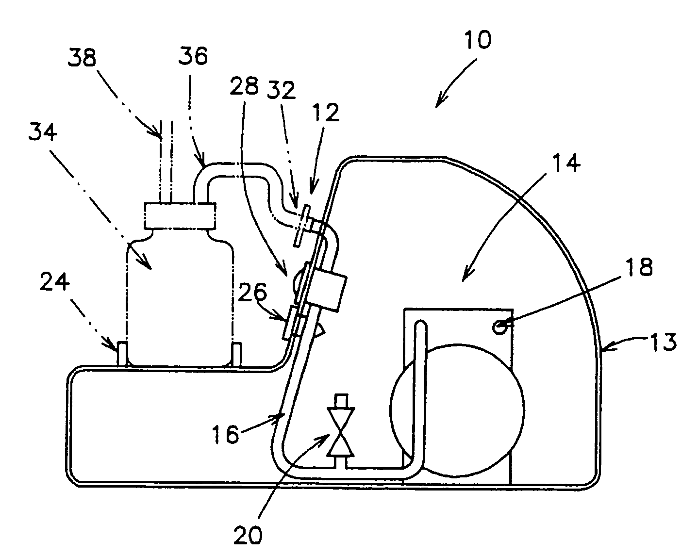
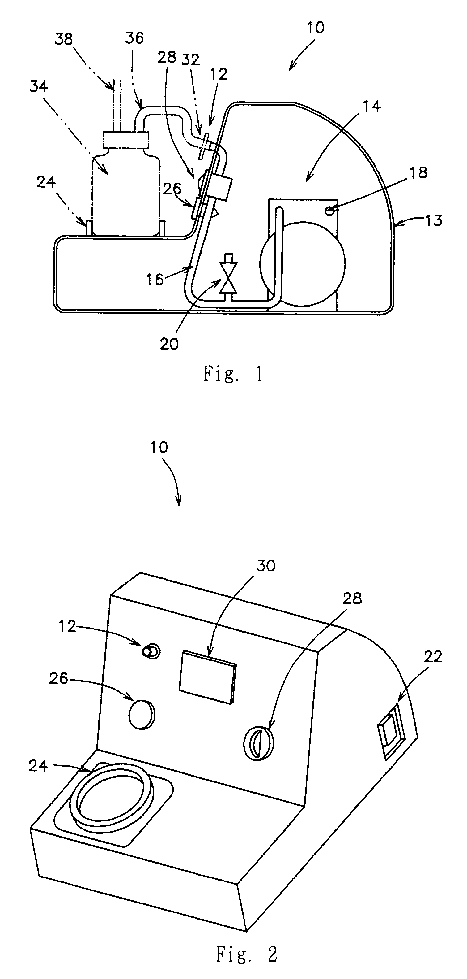
[0050]FIGS. 1 and 2 show a particularly preferred embodiment of the medical aspirator in accordance with the present invention. FIG. 1 is a longitudinal sectional view schematically showing a main part of the medical aspirator, and FIG. 2 is an external perspective view thereof. A medical aspirator 10 includes an aspiration port 12, a reciprocating type electric pump 14 for performing vacuum aspiration, a ventilation path 16 for connecting the aspiration port 12 and the electric pump 14, and an exhaust port 18. An atmospheric pressure obtaining release valve 20 for releasing a negative pressure in the ventilation path 16 to obtain atmospheric pressure therein, is provided in a position branched from the ventilation path 16.

[0051]In addition, the medical aspirator 10 also includes annular bottle fixing means 24, which projects in the shape of a base in a lower front part of the medical aspirator 10 and forms a place for putting an aspirate sampling bottle 34 thereon, and which is use...

second embodiment

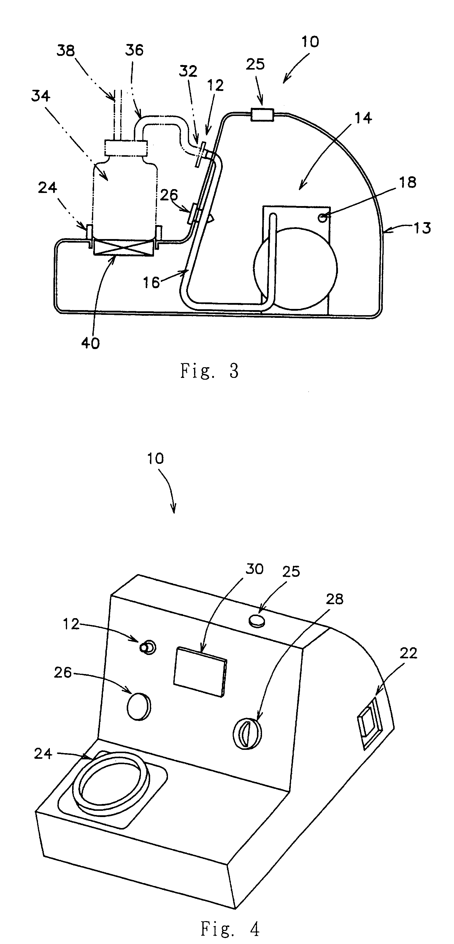
[0068]FIGS. 3 and 4 show a particularly preferred second embodiment of the medical aspirator in accordance with the present invention. FIG. 3 is a longitudinal sectional view schematically showing a main part of the medical aspirator, and FIG. 4 is an external perspective view thereof. A medical aspirator 10 includes an aspiration port 12, an electric pump 14 for performing vacuum aspiration, a ventilation path 16 for connecting the aspiration port 12 and the electric pump 14, and an exhaust port 18.

[0069]In addition, the medical aspirator 10 also includes annular bottle fixing means 24, which projects in the shape of a base in a lower front part of the medical aspirator 10 and forms a place for putting an aspirate sampling bottle 34 thereon, and which is used for holding the lower circumference of the aspirate sampling bottle 34 to fix the same. Further, bottle illumination means 26 is provided in an upper front part of a body case 13 so as to face the fixing position (bottle fixin...


PUM


Abstract

A medical aspirator including an aspiration port, a reciprocating type electric pump for performing vacuum aspiration, a ventilation path which connects the aspiration port and the electric pump, an exhaust port, and an atmospheric pressure obtaining release valve for releasing a negative pressure in the ventilation path to obtain atmospheric pressure therein. The medical aspirator is particularly useful for percutaneous thrombus removal operation. A diaphragm pump is used as the electric pump. An electromagnetic valve is used as the atmospheric pressure obtaining release valve. The atmospheric pressure obtaining release valve is opened and closed in association with stopping and starting of the electric pump. A cell is provided as an internal power supply.

Description

BACKGROUND OF THE INVENTION[0001]1. Field of the Invention[0002]The present invention relates to a medical aspirator for aspirating, for example, thrombus, phlegm, and a body fluid such as blood.[0003]2. Related Background Art[0004]Conventionally, medical aspirators have been used in wide fields such as intraoral treatment for a patient at home or a patient in a hospital and aspiration of a body fluid such as blood at the time of a surgical operation.[0005]However, these medical aspirators have a significant problem in that they are inferior in portability.[0006]First, a first point concerning the problem of portability will be hereinafter described.[0007]In general, in a medical aspirator, a reciprocating type electric pump has a larger startup load compared with a rotary electric pump. This is because startup energy loss of a mechanism for converting a rotational movement into a reciprocating movement is large. Therefore, special attention should be paid to the medical aspirator s...

Claims


Application Information

Patent Timeline
Patent Type & Authority Patents(United States)
IPC IPC(8): A61M1/00A61M27/00
CPCA61M1/0072A61M1/0066A61M1/80A61M1/82
Inventor KOBAYASHI, SUSUMUTEJIMA, TOMOYUKI
Owner NIPRO CORP
Why Eureka
Try Eureka