Dual buck-boost converter with single inductor

a converter and inductor technology, applied in the field of dual buck-boost converters, can solve the problems of reducing the overall reducing the efficiency of the power converter, and being less efficient in power density and device utilization, so as to increase the pulse width of a single switching operation, reduce the output voltage, and increase the output voltage

Active Publication Date: 2007-10-02
TEXAS INSTR INC
View PDF1 Cites 277 Cited by
  • Summary
  • Abstract
  • Description
  • Claims
  • Application Information

AI Technical Summary

Benefits of technology

[0013]According to an advantage of the present invention, a surge at either of the power converter outputs is balanced and corrected within a few control cycles where the input switches are appropriately switched. In addition, if either of the outputs sags below a desired value, the change is compensated and corrected within several control cycles by appropriately switching the input switches. The input switches can have differing on times to adjust the positive or negative output voltage.
[0014]According to an aspect of the present invention, the power converter runs in discontinuous mode. A switch duty cycle is modified during a control cycle to compensate variations in output voltages for either a negative or positive output voltage.
[0015]According to another aspect of the present invention, the input switches are complementary bipolar switches. In accordance with a particular embodiment of the present invention, the switches and other solid state devices, such as diodes, for example, are contained within an integrated circuit (IC), that also includes control circuitry. In accordance with this embodiment, power capacitors and a single inductor are supplied as external components to the IC.
[0016]According to another aspect of the present invention, a PNP switch on an input to the power converter is switched off earlier or later than an NPN switch on another input to the power converter. The switches are coupled together through a single inductor, and are operated to provide power to the high and low side outputs in every switching cycle.
[0017]According to a method of the present invention, pulse widths of a single switching operation are increased to increase output voltage, and decreased to decrease output voltage. If a positive voltage output becomes higher than the corresponding negative voltage output, the input switch for the negative voltage receives a shorter width pulse. If the negative voltage becomes higher than the corresponding positive voltage output, the input switch associated with the negative output receives a longer width pulse. With this control method, the load is automatically balanced between the two outputs and a single inductor can be used.
[0018]In accordance with another aspect of the present invention, power converter input switches are controlled based on a differential and common mode feedback signal, applied to separate polarity input switching controls. One polarity switch operates based on a differential mode feedback signal, while the other polarity input operates on a common mode feedback signal. By providing the two different modes of feedback with the different polarities, the output of the power converter can be inherently or automatically balanced.

Problems solved by technology

The use of two inductors also adds cost to the circuit in terms of component cost and increased size that is realized in constructing the converter.
This alternate method uses one inductor, but suffers from being less efficient in power density and device utilization.
However, the load balancer typically draws extra power by shunting voltage or current, and reduces the overall efficiency of the power converter.

Method used


Image

  • Dual buck-boost converter with single inductor
  • Dual buck-boost converter with single inductor
  • Dual buck-boost converter with single inductor

Examples


Embodiment Construction

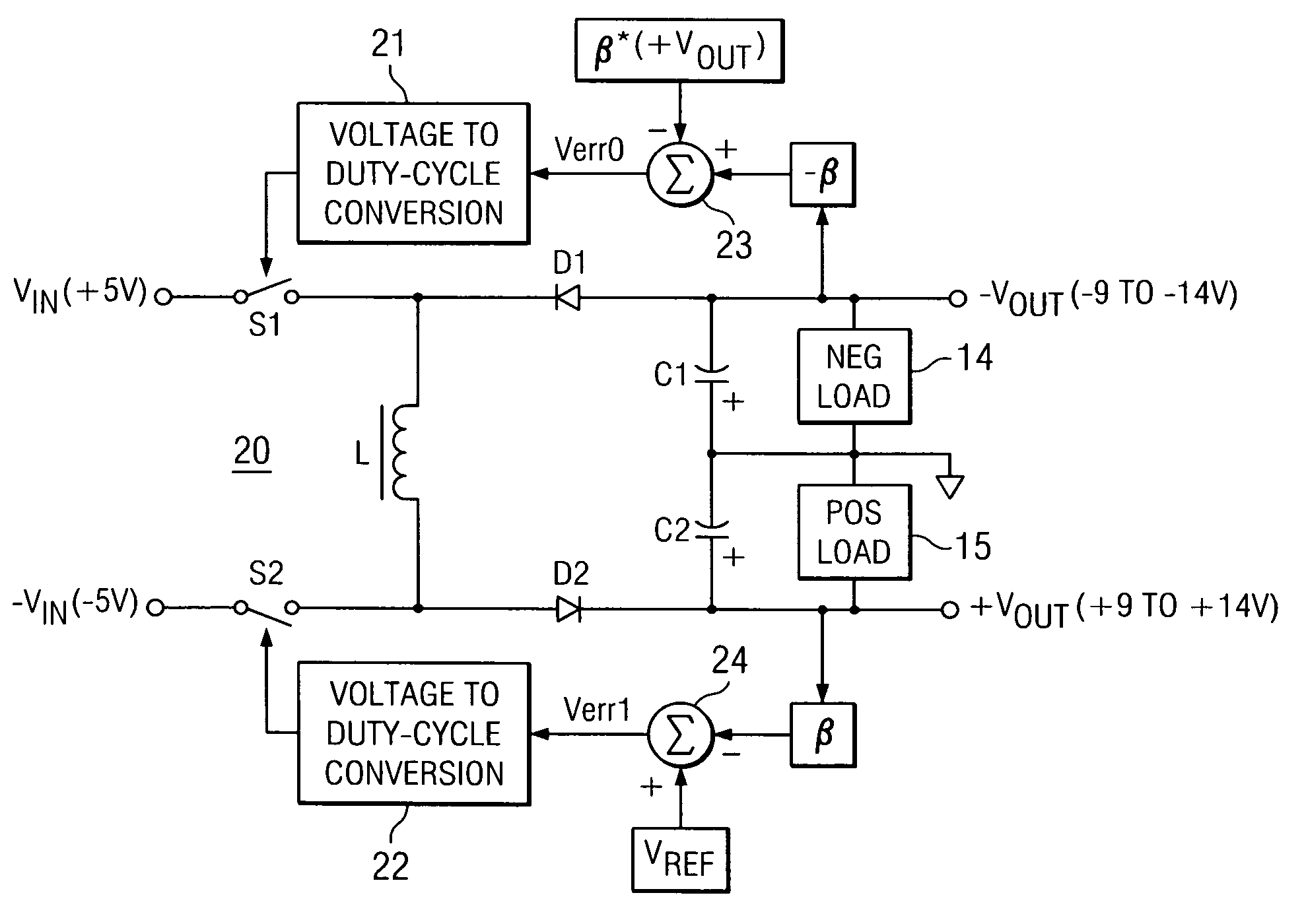
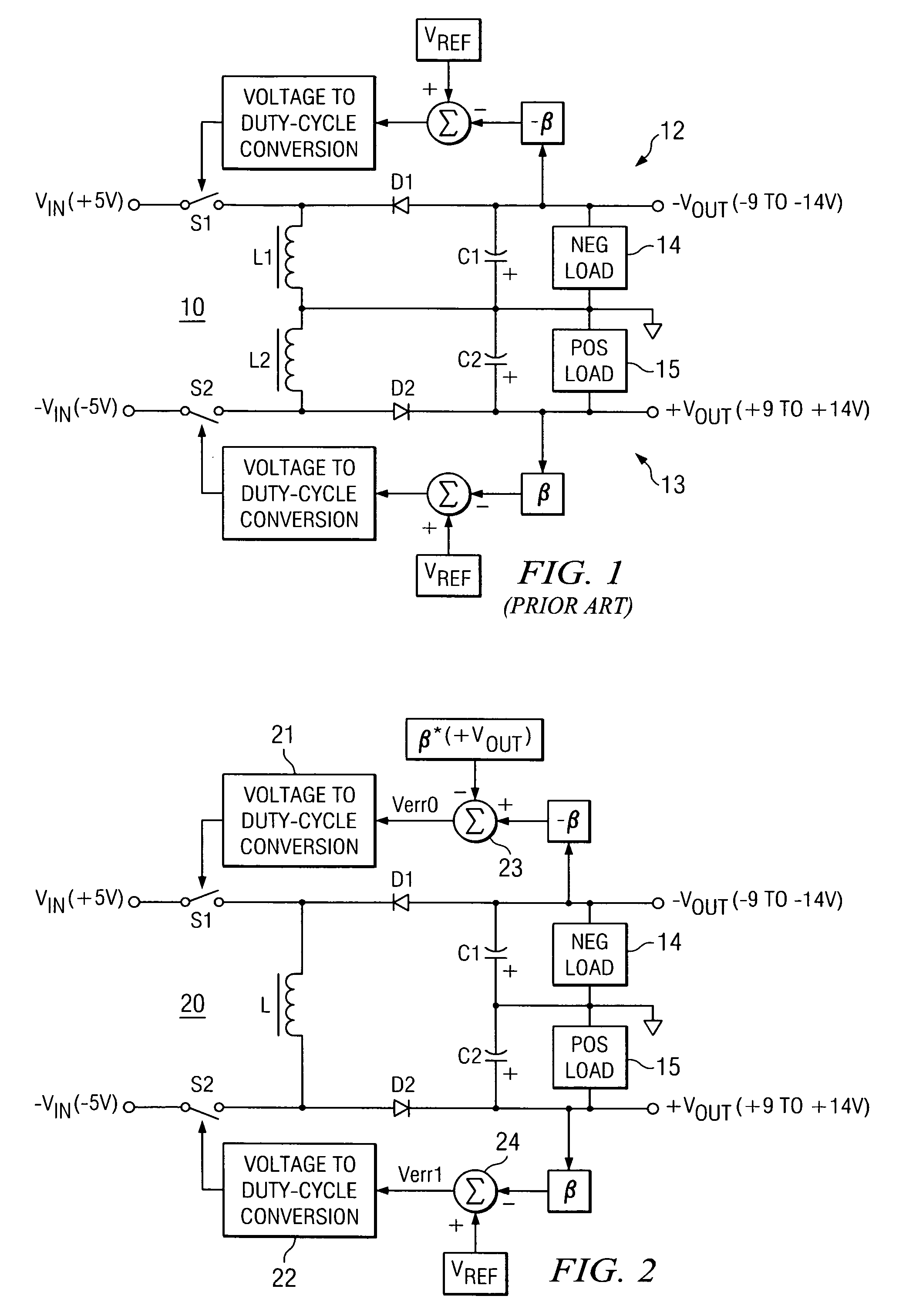
[0024]Referring now to FIG. 2, a circuit block diagram of a dual buck-boost converter in accordance with the present invention is illustrated as circuit 20. Circuit 20 includes a single inductor L coupled between switches S1 and S2 that are operable to switch input voltage for the separate inputs. In the embodiment illustrated by circuit 20, switch S switches +5V input into circuit 20 while switch S2 switches −5V input into circuit 20. Switches S1 and S2 are controlled by voltage to duty cycle converters 21 and 22, respectively. Converters 21 and 22 are driven based on an error signal generated by summing junctions 23 and 24, respectively.

[0025]Summing junction 24 operates by subtracting an output feedback value from reference voltage Vref to generate an error voltage Verr1. The output feedback value is determined from output voltage +Vout multiplied by a feedback ratio β. Accordingly, summing junction 24 realizes the error voltage feedback equation

Verr1=Vref−(+Vout*β).

Error voltage...


PUM


Abstract

A dual output buck-boost power converter operates with a single inductor to achieve high efficiency with automatic or inherent load balancing. Switches associated with the opposite polarity outputs are driven based on feedback signals, with one feedback signal being a reference voltage and another feedback signal being related to an opposite polarity output. The opposite polarity feedback signal is provided to a comparator with a reversed polarity to achieve a simple balanced control that maintains polarity outputs. The power converter delivers power to each output with each switching cycle and uses a single inductor to achieve high efficiency performance.

Description

CROSS REFERENCE TO RELATED APPLICATIONS[0001]N / ASTATEMENT REGARDING FEDERALLY SPONSORED RESEARCH OR DEVELOPMENT[0002]N / ABACKGROUND OF THE INVENTION[0003]1. Field of the Invention[0004]The present invention relates generally to power converters, and relates more particularly to a dual buck-boost power converter with independent regulation.[0005]2. Description of Related Art[0006]Dual buck-boost converter topologies are available for a number of applications. Typically, two different power supplies create two separate outputs. The two separate outputs are often a positive voltage output and a negative voltage output.[0007]Referring to FIG. 1, a buck-boost converter with two inputs and two outputs is illustrated as circuit 10. Circuit 10 includes two of each component, such as two switches S1, S2, two diodes D1, D2, two inductors L1, L2 and two capacitors C1, C2. The two power supplies, indicated as circuit 12 and 13, each have a separate feedback circuit to provide a closed loop contr...

Claims


Application Information

Patent Timeline
Patent Type & Authority Patents(United States)
IPC IPC(8): G05F1/577G05F1/24
CPCH02M3/1582H02M2001/009H02M1/009
Inventor KINDER, RUSSELL M.CORSI, MARCO
Owner TEXAS INSTR INC
Why Eureka
Try Eureka