Multilayer filter

a filter and multi-layer technology, applied in the field of multi-layer filters, can solve the problems of degrading the cancelling action, and achieve the effects of preventing an electric current from rapidly flowing, increasing the melting point of the conductor portion, and increasing the dc resistance of the inductor par

Active Publication Date: 2007-10-02
TDK CORPARATION
View PDF15 Cites 19 Cited by
  • Summary
  • Abstract
  • Description
  • Claims
  • Application Information

AI Technical Summary

Benefits of technology

[0006]The present invention has been accomplished in view of the above circumstances and an object of the invention is therefore to provide a multilayer filter capable of preventing an electric current rapidly flowing by virtue of the varistor effect, from passing as noise, upon application of noise of a high voltage over the varistor voltage to its input.
[0008]This multilayer filter comprises the inductor part and the varistor part, and the inductor part has the DC resistance of 4 Ω-100 Ω. This achieves the effect of preventing an electric current rapidly flowing by virtue of the varistor effect, from passing as noise, upon application of noise of a high voltage over the varistor voltage to the input (so called dumping effect).
[0009]In the multilayer filter according to the present invention, preferably, the conductor portions are made of a material containing silver (Ag) and palladium (Pd). This permits the DC resistance of the inductor part to be securely set higher, for example, in comparison with a case where the conductor portions are made of a material consisting primarily of Ag. Furthermore, the melting point of the conductor portions can be securely increased, for example, in comparison with the case where the conductor portions are made of the material consisting primarily of Ag. For this reason, when the laminate is baked in a production process of the multilayer filter, the laminate can be integrally baked at a baking temperature of the second multilayer portion generally higher than that of the first multilayer portion.
[0010]In the multilayer filter according to the present invention, preferably, an intermediate layer having a coefficient of thermal expansion between that of the insulator layers and that of the varistor layers is laid between the first multilayer portion and the second multilayer portion. This can prevent occurrence of a crack or delamination in the laminate due to the difference between the coefficient of thermal expansion of the insulator layers and the coefficient of thermal expansion of the varistor layers. Furthermore, it can prevent diffusion of a component from the insulator layers into the varistor layers and diffusion of a component from the varistor layers into the insulator layers and enables the characteristics of the insulator layers and the characteristics of the varistor layers to be maintained at respective predetermined characteristics.

Problems solved by technology

In the multilayer filter as described above, however, there are cases where the electric current rapidly flowing by virtue of the varistor effect passes as noise through the multilayer filter.
However, for example, in a case where the multilayer filter is downsized, so as to decrease the capacitance of the varistor part, the noise cancellation action degrades, so that the rapidly flowing current can pass as noise through the multilayer filter.

Method used


Image

  • Multilayer filter
  • Multilayer filter
  • Multilayer filter

Examples


first embodiment

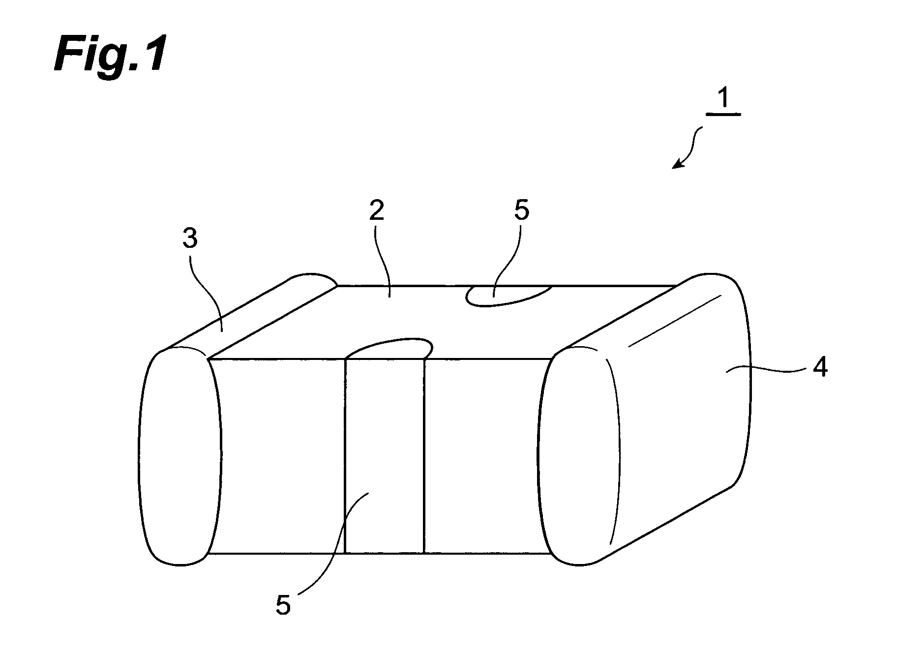
[0022]As shown in FIG. 1, a multilayer filter 1 has a laminate 2 of a rectangular parallelepiped shape. In the laminate 2, an input terminal electrode (first terminal electrode) 3 and an output terminal electrode (second terminal electrode) 4 are formed at the both ends of the laminate 2 in the longitudinal direction thereof, and a pair of ground terminal electrodes (third terminal electrodes) 5 are formed on two side faces in the direction perpendicular to the longitudinal direction.

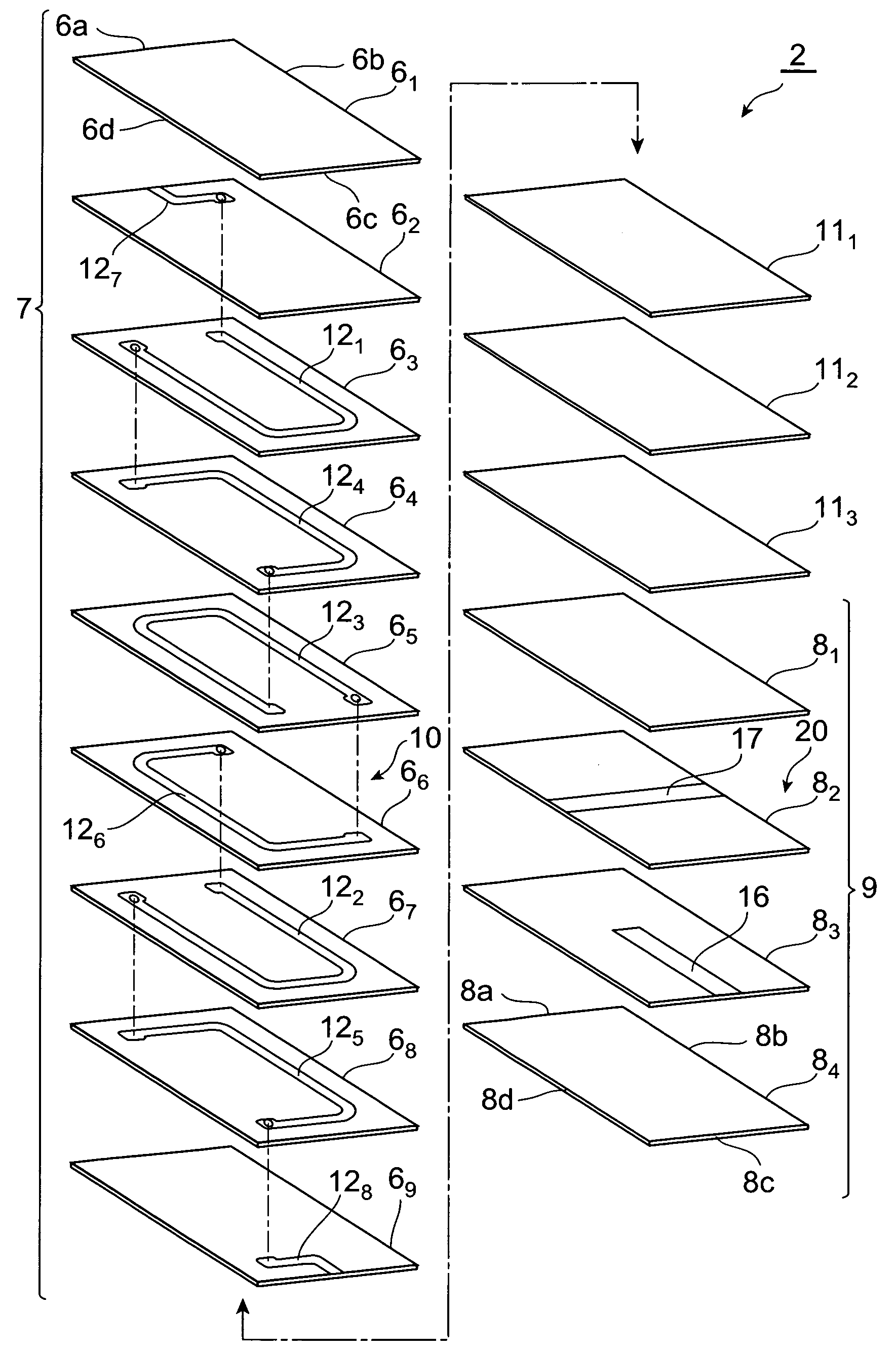
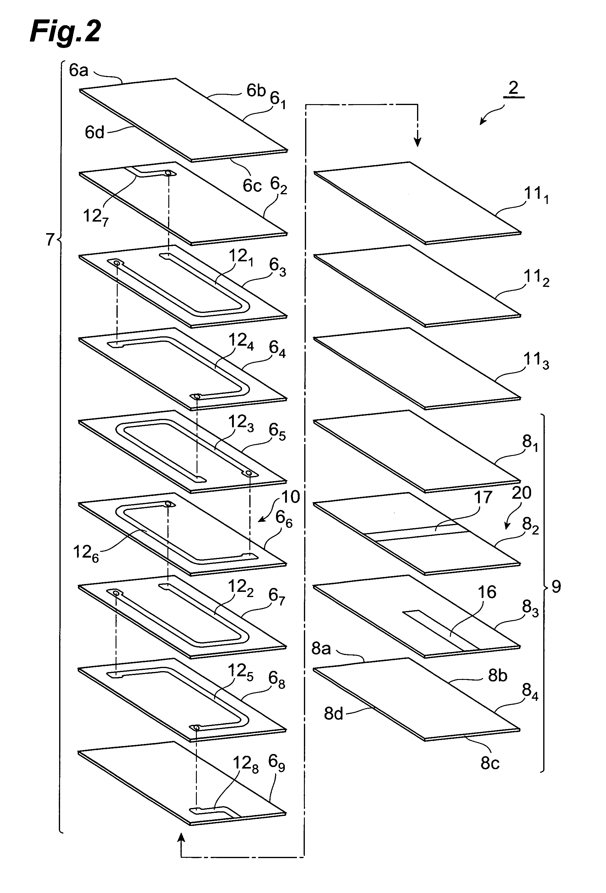
[0023]The laminate 2, as shown in FIG. 2, is constructed so that a multilayer portion (first multilayer portion) 7 consisting of a stack of insulator layers 61-69, a multilayer portion (second multilayer portion) 9 consisting of a stack of varistor layers 81-84, and a plurality of intermediate layers 111-113 located between the multilayer portion 7 and the multilayer portion 9 are stacked in a stack direction of the multilayer portions 7, 9.

[0024]The insulator layers 61-69 are made of an electrically in...

second embodiment

[0043]The multilayer filter 1 according to the second embodiment is different in the configuration of the multilayer portion 9 from the multilayer filter 1 according to the first embodiment.

[0044]Namely, the multilayer portion 9 is comprised of a stack of varistor layers 81-86, as shown in FIG. 4. A hot electrode 161, one end of which reaches the edge 8c to be electrically connected to the output terminal electrode 4, is formed on the varistor layer 83 so as to extend along the edge 8b in the central region thereof, and a hot electrode 162, one end of which reaches the edge 8a to be electrically connected to the input terminal electrode 3, is formed on the varistor layer 85 so as to extend along the edge 8b in the central region thereof. Ground electrodes 17, two ends of which reach the edge 8b and the edge 8d to be electrically connected to the ground terminal electrodes 5, are formed on the varistor layers 82, 84, respectively, so as to extend along the edge 8a in the central regi...

third embodiment

[0047]The multilayer filter 1 according to the third embodiment is different from the multilayer filter 1 according to the first embodiment in that the filter is constructed in an array form.

[0048]Namely, as shown in FIG. 6, four pairs of terminal electrodes 3,4 are juxtaposed on the two end faces of the laminate 2 in the direction perpendicular to the longitudinal direction thereof. As shown in FIG. 7, four sets of inductor parts 10 are juxtaposed in the multilayer portion 7, and four sets of varistor parts 20 are juxtaposed in the multilayer portion 9.

[0049]The multilayer filter 1 constructed as described above constitutes four sets of L-shape circuits of the inductor parts 10 and the varistor parts 20, as shown in FIG. 8. The multilayer filter 1 constructed in the array form as described above also achieves the dumping effect.


PUM


Abstract

An objective is to provide a multilayer filter capable of preventing an electric current rapidly flowing by virtue of varistor effect, from passing as noise, upon application of noise of a high voltage over a varistor voltage to its input. A multilayer filter has an inductor part 10 and a varistor part 20 in a laminate 2, and the inductor part 10 has the DC resistance of 4 Ω-100 Ω. This prevents an electric current rapidly flowing by virtue of the varistor effect, from passing as noise, upon application of noise of a high voltage over the varistor voltage to the input.

Description

BACKGROUND OF THE INVENTION[0001]1. Field of the Invention[0002]The present invention relates to a multilayer filter.[0003]2. Related Background Art[0004]A conventionally known multilayer filter is one having an inductor part and a varistor part (e.g., Japanese Patent No. 2716022). The multilayer filter of this type exhibits the varistor effect with rapid flow of an electric current upon application of noise of a high voltage over a varistor voltage to its input.SUMMARY OF THE INVENTION[0005]In the multilayer filter as described above, however, there are cases where the electric current rapidly flowing by virtue of the varistor effect passes as noise through the multilayer filter. Since the varistor part originally has some capacitance, it has noise cancellation action to prevent the rapidly flowing current from becoming noise. However, for example, in a case where the multilayer filter is downsized, so as to decrease the capacitance of the varistor part, the noise cancellation acti...

Claims


Application Information

Patent Timeline
Patent Type & Authority Patents(United States)
IPC IPC(8): H01G4/06
CPCH03H1/0007H03H2001/0085H01C7/10H01F27/00
Inventor SATO, TAKAHIROYOSHIDA, KENTAROORIHARA, MASASHIKUMAGAI, SHUMI
Owner TDK CORPARATION
Why Eureka
Try Eureka