Video pedestal network

a technology of video pedestal and network, applied in the field of digital information delivery, can solve the problems of inability to achieve practicality, intrinsically require large bandwidth, and development of necessary infrastructure, and achieve the effects of low cost, low cost, and low cos

Inactive Publication Date: 2007-10-02
IRDETO USA
View PDF68 Cites 29 Cited by
  • Summary
  • Abstract
  • Description
  • Claims
  • Application Information

AI Technical Summary

Benefits of technology

[0011]Using the information received from the subscriber unit, the intermediate interface selects the desired digital service from a multitude of services available in a broadband link coupled to the interfaces input and transmits it to the subscriber unit over a bandwidth-constrained link. The bandwidth-constrained link may be implemented with existing infrastructure, yet the subscriber unit may readily access a wide variety of digital services available on the broadband network. The present invention thus combines universal broadband access with low cost.
[0012]In accordance with the invention, a service provider may offer broadcast services over the network in addition to point-to-point interactive services. The broadcast services may be offered without requiring multiple point-to-point

Problems solved by technology

One of the main obstacles to the introduction of these services is development of the necessary infrastructure for delivering digital video information to the subscribers' premises.
Video services, even with the use of modern compression standards such as MPEG-1 and MPEG-2, intrinsically require large bandwidths.
Nonetheless, this approach is practically infeasible today since the cost of laying fiber or coaxial cable to each home is prohibitive.
Additionally, the time required to deploy such an infrastructure over a large geographic area makes the scheme even more unattractive.
Again, for those network providers that do not already have such an infrastructure installed, costs are prohibitive because coaxial cable must be brought to each home.
Furthermore, the use of TDM coupled with highly limited bandwidth gives rise to a large latency in the return channel.
Network security is another drawback of the HFC architecture as several users share a single coaxial cable,

Method used


Image

  • Video pedestal network
  • Video pedestal network
  • Video pedestal network

Examples


Embodiment Construction

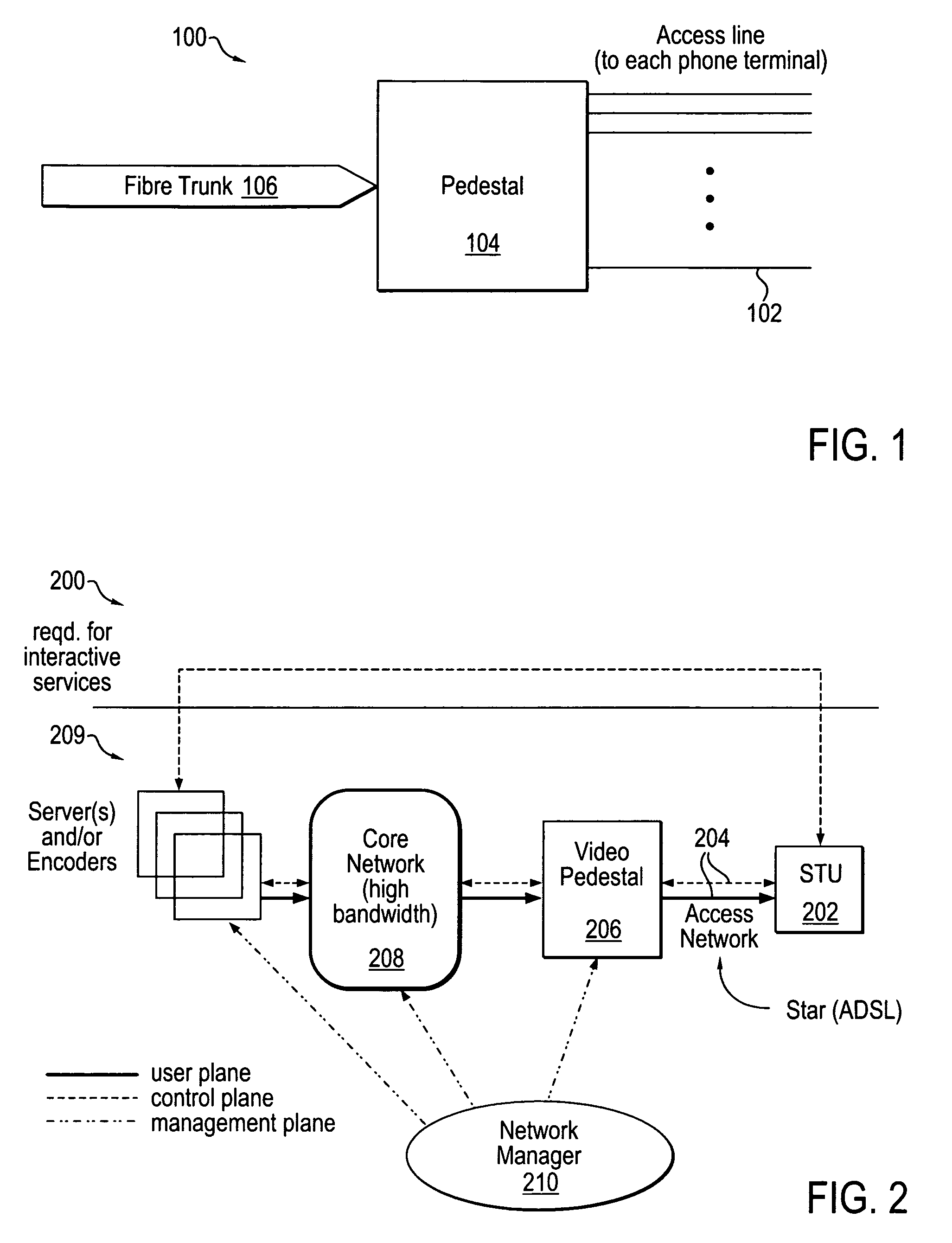
[0039]The present invention provides a system for distributing digital information from a broadband digital information source to one or more subscriber units. An exemplary digital information distribution system in accordance with the present invention includes a plurality of digital information servers coupled to a plurality of Subscriber Terminal Units (STUs) or subscriber units via a plurality of links.

[0040]A link provides a mechanism for transferring data from one entity, called the source, to another entity, called the receiver. A link is capable of transferring data in either direction or both directions simultaneously. An entity that is a receiver for data travelling along one direction in a link can be the source for data travelling along the opposite direction in the same link. Likewise, an entity that is a receiver for one link can be a source for another link. For example, if data passes down one link into a receiver and continues into another link, the same entity that...


PUM


Abstract

An architecture for distributing digital information to subscriber units wherein selection from among multiple digital services is accomplished by transmitting a tuning command from a subscriber unit to an intermediate interface. The intermediate interface selects the desired service from a broadband network and transmits it to the subscriber unit over a bandwidth-constrained access line. The bandwidth-constrained access line may be implemented with existing infrastructure, yet the subscriber unit may access a wide variety of digital information available on the broadband network. Universal broadband access is thus provided at low cost. Output bandwidth of broadcast equipment may also be optimized.

Description

STATEMENT OF RELATED APPLICATIONS[0001]This application is a continuation and claims the benefit of U.S. application Ser. No. 08 / 568,605, filed Dec. 5, 1995 now U.S. Pat. No. 5,940,738, the disclosure of which is incorporated by reference.[0002]This application is a continuation-in-part of Ser. No. 08 / 451,264, filed May 26, 1995. Now U.S. Pat. No. 5,793,410BACKGROUND OF THE INVENTION[0003]The present invention relates generally to delivery of digital information to subscriber premises and more particularly to providing this access without substantial new wiring expense.[0004]The delivery of digital video services to the home represents one important aspect of the much publicized “information highway.” These services include HDTV, video-on-demand (VOD), near-video-on-demand (NVOD) providing staggered program starting times, interactive video services (IVS), and other digital variants of conventional broadcast services.[0005]One of the main obstacles to the introduction of these servi...

Claims


Application Information

Patent Timeline
IPC IPC(8): H04N7/18H04N7/16H04N7/173H04H20/38H04H20/81H04H60/94H04L12/28H04L12/46H04L12/56H04M11/06H04N7/10H04N7/14
CPCH04H20/38H04N21/6587H04H60/94H04L12/2801H04L12/2856H04L12/2883H04L12/4633H04L47/2408H04M11/062H04N7/108H04N7/148H04N7/173H04N7/17336H04N7/17354H04N21/222H04N21/2362H04N21/2365H04N21/4347H04N21/47202H04N21/47208H04N21/6125H04N21/6137H04N21/6377H04N21/64307H04N21/64784H04N21/658H04N21/6581H04H20/81H04L5/16
Inventor RAO, R. PADMANABHA
Owner IRDETO USA
Why Eureka
Try Eureka