Polishing disk for a tool for the fine machining of optically active surfaces on spectacle lenses in particular

a technology of optical active surfaces and polishing disks, which is applied in the field of polishing disks for fine machining of optical active surfaces, can solve the problems of no longer any partial solidification of polishing film and detrimental to the surface quality obtained, and achieves the effects of maximizing the holding volume of the reservoir, simple production, and easy production of polishing film

Active Publication Date: 2007-10-09
SATISLOH GMBH
View PDF21 Cites 28 Cited by
  • Summary
  • Abstract
  • Description
  • Claims
  • Application Information

AI Technical Summary

Benefits of technology

[0009]The opening according to the invention in the polishing film ensures a fluid connection between an inner region of the foam layer, which is saturated with polishing agent in the manner of a sponge during the machining operation, and the outer surface of the polishing film which is in machining engagement with the surface of the workpiece that is to be machined. The liquid polishing agent can thus circulate better and can also pass from the interior of the polishing disk to the engagement regions between the polishing film and the surface of the workpiece that is to be machined, as a result of which better rinsing and cooling is ensured at these engagement regions on account of increased wetting of the polishing film and a more uniform film of polishing agent. Accordingly, there is no longer any partial solidification of the polishing film which is detrimental to the surface quality obtained, so that the polishing disk can be used for a longer period compared to the above prior art.
[0023]In order to improve the ability of the polishing disk to adapt to the macro-geometry of the surface to be machined, via the elasticity of the foam layer, the support body may furthermore be made of a rubber-elastic material with a Shore A hardness in the range of preferably 60 to 80.

Problems solved by technology

Accordingly, there is no longer any partial solidification of the polishing film which is detrimental to the surface quality obtained, so that the polishing disk can be used for a longer period compared to the above prior art.

Method used


Image

  • Polishing disk for a tool for the fine machining of optically active surfaces on spectacle lenses in particular
  • Polishing disk for a tool for the fine machining of optically active surfaces on spectacle lenses in particular
  • Polishing disk for a tool for the fine machining of optically active surfaces on spectacle lenses in particular

Examples


Embodiment Construction

OF EMBODIMENTS

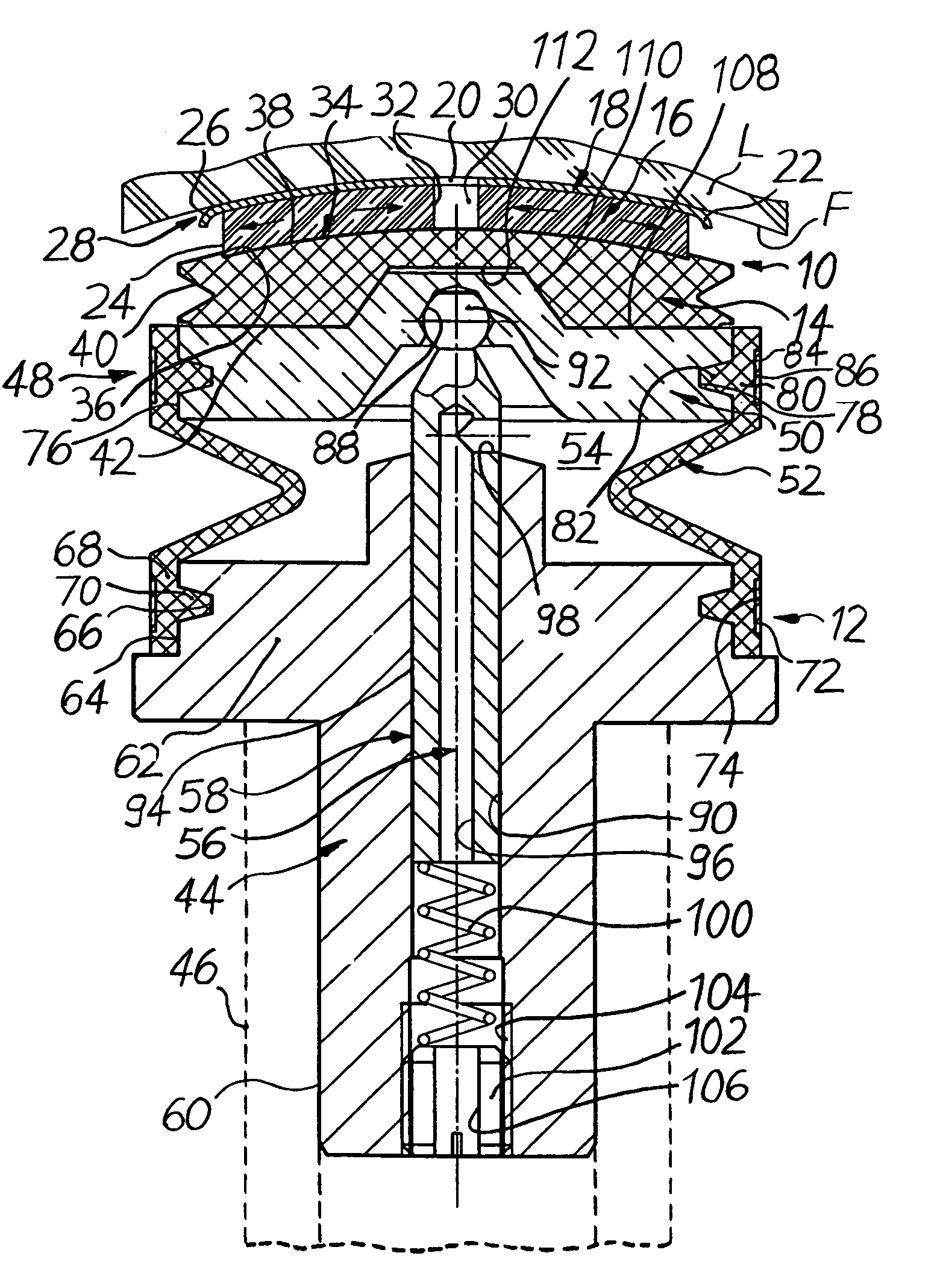
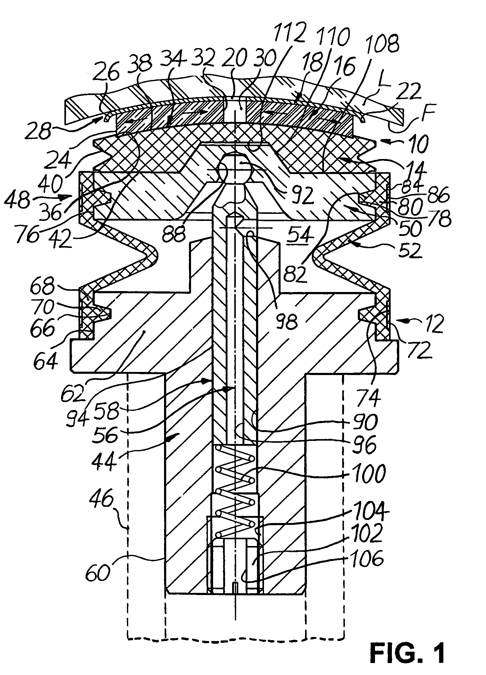
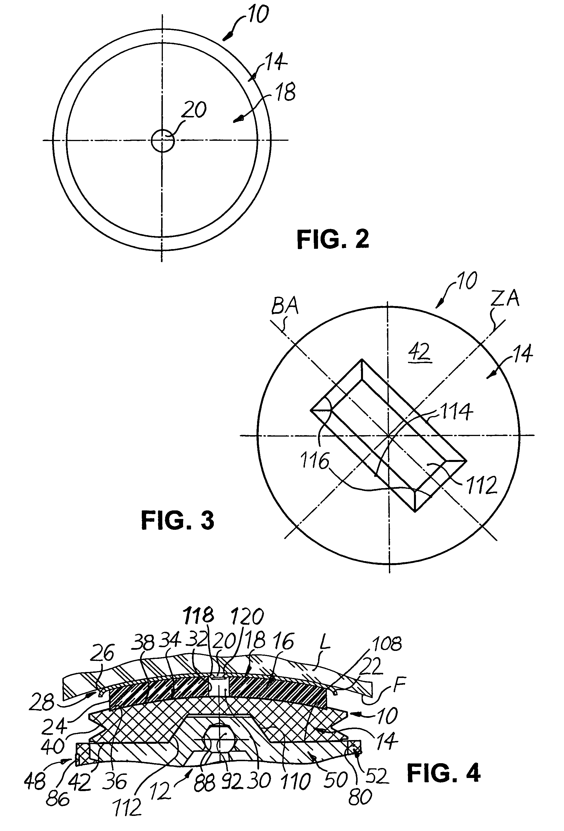
[0033]As shown in FIG. 1, a polishing disk 10 for a tool 12 for the fine machining of optically active surfaces F on spectacle lenses L in particular comprises a support body 14, to which a foam layer 16 is attached, wherein a polishing film 18 bears against said foam layer. It is essential that the polishing film 18 is provided with at least one opening 20 in a central region, as will be described in more detail below.

[0034]The polishing film 18, also referred to as a “polishing pad”, which forms the active machining part of the tool as shown in FIG. 1, is a commercially available, elastic and wear-resistant fine grinding or polishing agent support, such as for example a PUR (polyurethane) film which has a thickness of 0.5 to 1.4 mm and a Shore D hardness of between 12 and 45. The polishing film 18 is designed to be slightly thicker if prepolishing is to be carried out using the polishing disk 10, and on the other hand is designed to be slightly thinner in the case of...


PUM


Abstract

A polishing disk for a tool for the fine machining of optically active surfaces on spectacle lenses in particular is disclosed, which comprises a support body, to which a foam layer is attached, wherein a polishing film bears against the foam layer. The polishing film is provided with at least one opening in a central region. During machining, the opening ensures pressure equalization and makes liquid polishing agent available from inside the foam layer, as a result of which better rinsing and cooling of otherwise disadvantaged regions of the polishing disk is achieved. As a result, a polishing disk of simple and cost-effective design is proposed, which is much more durable than the prior art while achieving high surface qualities.

Description

TECHNICAL FIELD[0001]The present invention relates to a polishing disk for a tool for the fine machining of optically active surfaces. Such polishing disks are used in bulk in the manufacture of prescription spectacle lenses in particular.[0002]When the term “spectacle lenses” is used below by way of example of workpieces with optically active surfaces, this is intended to refer not only to spectacle lenses made of mineral glass but also to spectacle lenses made of all other customary materials, such as polycarbonate, CR 39, Hi Index, etc., that is to say also plastic.PRIOR ART[0003]The machining of the optically active surfaces of spectacle lenses can roughly be split into two machining phases, namely firstly the premachining of the optically active surface to produce the prescription macro-geometry and then the fine machining of the optically active surface to eliminate any traces left behind by the premachining and obtain the desired micro-geometry. While the premachining of the ...

Claims


Application Information

Patent Timeline
Patent Type & Authority Patents(United States)
IPC IPC(8): B24B29/00
CPCB24B13/012B24B13/02Y10S451/921
Inventor URBAN, LOTHARPHILIPPS, PETER
Owner SATISLOH GMBH
Why Eureka
Try Eureka