Power factor correction circuits

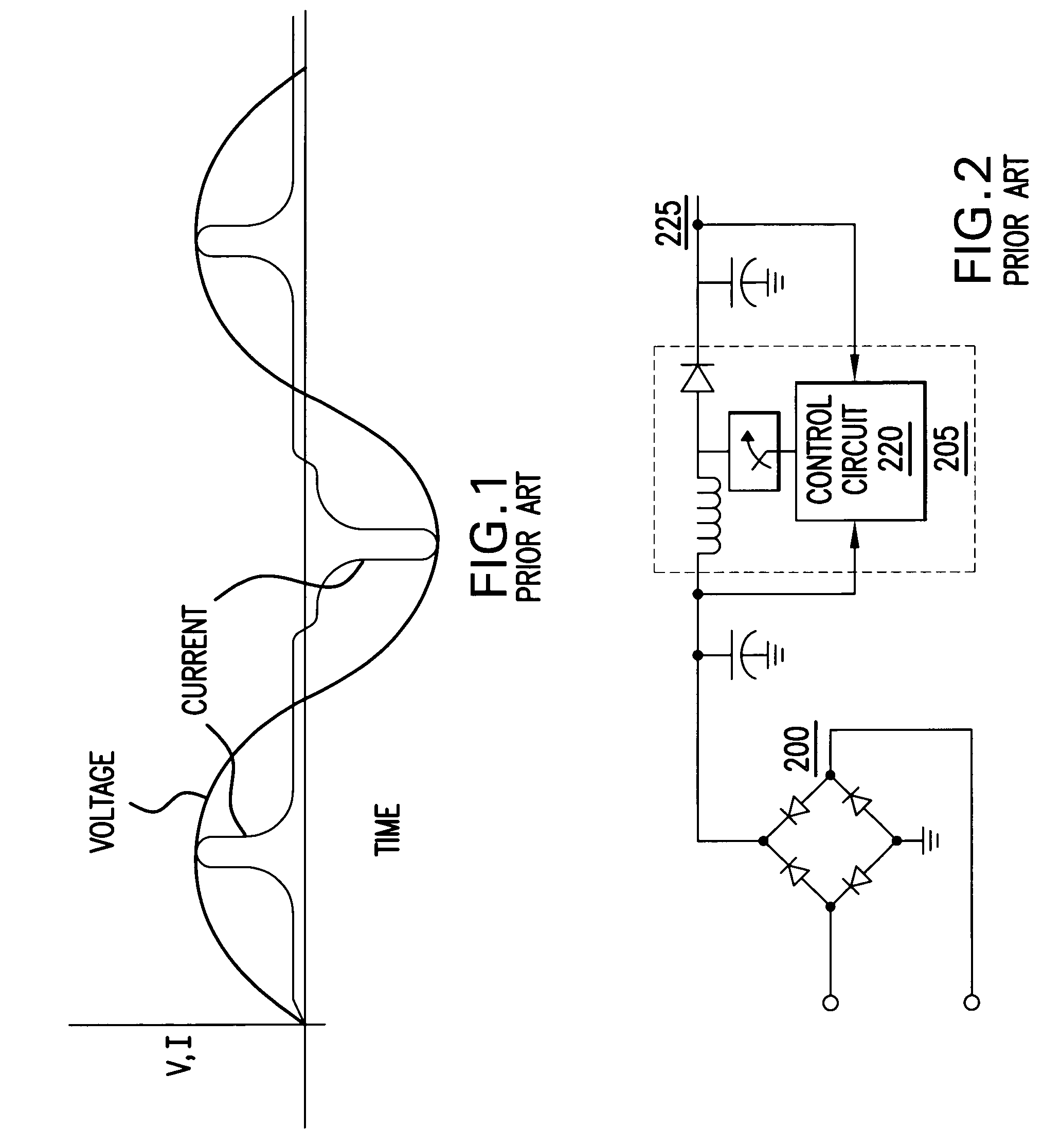
a power factor and circuit technology, applied in the field of power adapters, can solve the problems of reducing the real power that the network can supply, the sine wave to collapse around its peak, and the considerable concern of the electricity supply industry

Inactive Publication Date: 2007-10-09
COMARCO WIRELESS TECH
View PDF6 Cites 70 Cited by
  • Summary
  • Abstract
  • Description
  • Claims
  • Application Information

AI Technical Summary

Problems solved by technology

The explosive growth in consumer electronics is causing the electricity supply industry considerable concern.
The electricity generator, with no power factor correction, must supply energy at the top / peak of the sine wave rather than throughout the cycle, which can cause the sine wave to collapse around its peak.
The electricity generator sees the phase lag between the current and voltage, together with the harmonics from peaky loads, as combining to provide require rms currents, which in turn reduces the real power that the network can supply.
Varying loads at the consumer end of the line produces fluctuations throughout the local line and these fluctuations cause undersirable consequences, such as causing lighting sources to flicker.
The large spikes in the current waveform are caused because of the switching power supplies' use of the rectifier bridge / smoothing capacitor circuits.
However, the circuit utilizes at least five diodes, four of which are located in the bridge rectifier, and diodes are lossy components, which decreases the power efficiency of the circuit.

Method used


Image

  • Power factor correction circuits
  • Power factor correction circuits
  • Power factor correction circuits

Examples


Embodiment Construction

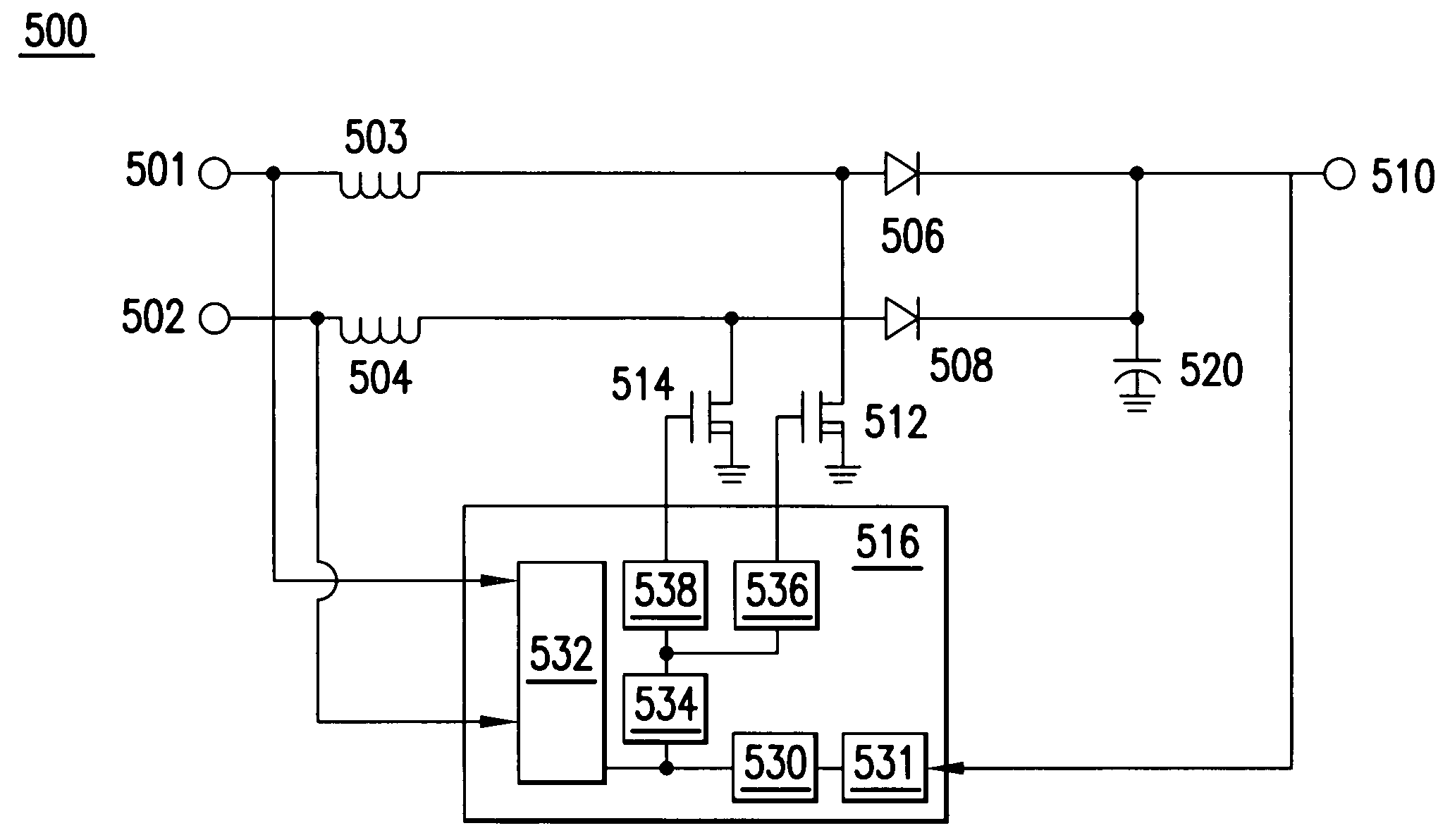
[0031]FIG. 3 illustrates a bi-directional boost circuit for power factor correction according to an embodiment of the present invention. The boost power factor conversion circuit may be utilized in an AC to DC power adapter or power converter. It is desirable for the power adapter to appear to the power supply line as a resistive load. In other words, the current waveform should be in phase and have approximately the same shape as the voltage waveform. This minimizes the demand on the utility provider because large, potentially instantaneous spikes of current demand may be avoided.

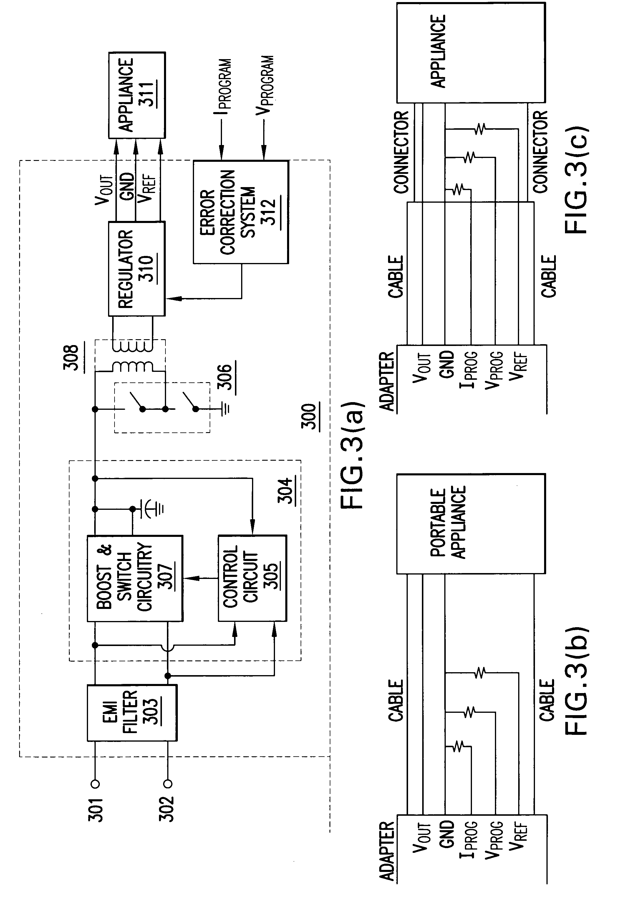
[0032]The power adapter 300 may include a pair of AC input terminals 301 and 302, an electronic magnetic interference (EMI) filter 303, a bi-directional boost circuit 304, a switching device 306, a transformer 308, a regulator 310, and an error correction system 312. The power adapter 300 may produce a power output having a regulated output voltage and a controlled output current.

[0033]The EMI filter 303 r...


PUM


Abstract

A bi-directional boost circuit for power factor correction includes a power factor control circuit and a pair of diodes, a pair of inductors, and a pair of switches. A first diode, a second diode, a first inductor, a second inductor, a first switch, and a second switch convert the AC input voltage, rectify the AC input voltage, and output an intermediate DC voltage. The power factor control circuit receives the AC input voltage and receives the intermediate DC voltage. The power factor control circuit regulates the DC output voltage. Based on the AC input voltage and the intermediate DC output voltage, the power factor control circuit controls an inductor current waveform by driving the first switch and the second switch to create a substantially sinusoidal current as seen by the power source that is in phase with the AC input voltage.

Description

BACKGROUND OF THE INVENTION[0001]1. Technical Field[0002]This invention relates to power adapters, and more specifically, to a system and method to correct power factor, i.e., the ratio of real power to apparent power.[0003]2. Description of the Related Arts[0004]The explosive growth in consumer electronics is causing the electricity supply industry considerable concern. The appliances or consumer electronics devices employ power supplies that draw current from the AC power line during the peak of the sine wave. Most of the appliances or consumer electronics device utilize a rectifier-bridge / smoothing capacitor circuit.[0005]Power factor is the ratio of real power to apparent power. In the United States, power is provided at approximately 120 Volts AC with a frequency of approximately 60 Hertz. In Europe and other areas, power is provided at approximately 240 Volts AC with a frequency of approximately 50 Hertz. In order to provide a maximum amount of usable energy or power, it is de...

Claims


Application Information

Patent Timeline
Patent Type & Authority Patents(United States)
IPC IPC(8): G05F1/00H02M7/217
CPCH02M1/4208H02M7/217Y02B70/126Y02B70/10
Inventor LANNI, THOMAS W.
Owner COMARCO WIRELESS TECH
Why Eureka
Try Eureka