Circuit for correcting part active power factor

A correction circuit and power factor control technology, applied in the field of power supply, can solve the problems of excessive interference power, increase the cost of frequency conversion control system, unsatisfactory improvement, etc., and achieve the best correction effect

Active Publication Date: 2008-12-17
HAIER GRP CORP +1
View PDF0 Cites 36 Cited by
  • Summary
  • Abstract
  • Description
  • Claims
  • Application Information

AI Technical Summary

Problems solved by technology

The problem of this kind of power factor correction circuit is: the switching frequency of the internal switching tube is very high (generally above 20K), so it will generate considerable electromagnetic interference during operation, which will make the interference voltage and interference power of the system exceed the standard. In order to suppress the

Method used


Image

  • Circuit for correcting part active power factor
  • Circuit for correcting part active power factor
  • Circuit for correcting part active power factor

Examples


Embodiment Construction

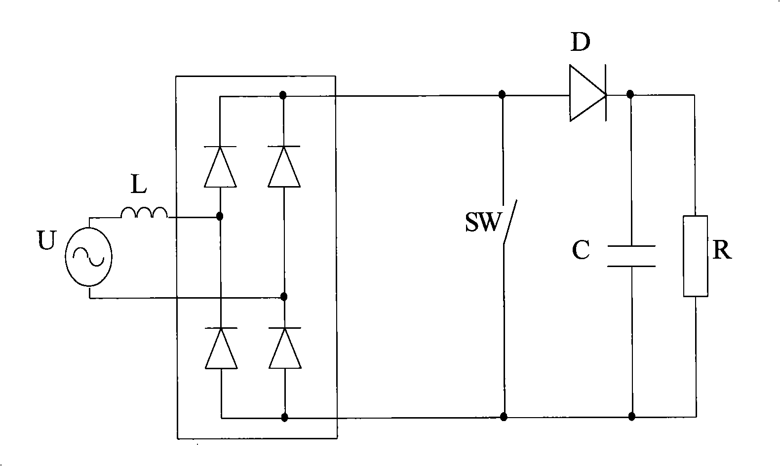
[0045] Please see Image 6 , which is a circuit diagram of a rectification circuit including a part of the active correction circuit according to the first embodiment of the present invention.

[0046] As shown in the figure, in this circuit, the AC input terminal of the bridge rectifier circuit ZT is connected to the mains Vi, and the filter capacitor C1 is connected in parallel between the positive and negative poles of the DC output terminal, and the current sampling is connected in series on the negative pole of the output terminal of the rectifier power supply ZT. Resistor SH1, the resistance value of the sampling resistor SH1 is very small, and its end away from the rectified power supply ZT is connected to the negative input terminal of the inverter circuit IPM, and serves as the power ground. The anode of the DC output terminal of the rectifier circuit ZT is connected to the inductor L1, and the other end of the inductor L1 is connected to the anode of the diode FRD. ...


PUM


Abstract

The invention discloses a partial active power factor correcting circuit, comprising a current detecting circuit, for real-time detecting the output current of a rectifying circuit; a power factor control unit, for obtaining the actual current waveform which reflects the real-time change of the current before the correction according to the current realtime value detected by the current detecting unit before the power factor correcting circuit starts working, and working out the continuous sine waveform as the expected current waveform with the same waveform, the same frequency and the continuous sine waveform according to the waveform; after obtaining the current waveform, the power factor control unit computes the difference between the expected current waveform and the real-time detected current actual measurement waveform, and controls the on/off of the controlled switch always in the ascending stage of the waveform and the moment with the largest difference, and controls the on/off of the controlled switch after delaying some time. The partial active power factor correcting circuit of the invention causes the actual current waveform consistent with the expected current waveform, which realizes the optimum correcting effect.

Description

technical field [0001] The invention relates to power supply technology, in particular to a partially active power factor correction circuit. Background technique [0002] In the power grid, various loads, especially non-linear loads, have a major impact on the quality of power grid power supply. For example, the power supply of many electrical appliances needs to convert the alternating current of the grid into direct current, and the pulsating current generated during the rectification process contains a large number of current harmonic components. These current harmonic components flow back into the grid, which will cause harmonic "pollution" to the grid. When the current flows through the line impedance, it will cause a harmonic voltage drop and distort the sine wave grid voltage. In addition, the generated harmonics also cause the power factor of the grid current to decrease, increase the loss of the distribution system conductors and transformers; and increase the har...

Claims


Application Information

Patent Timeline
IPC IPC(8): H02M1/42H02M1/12H02M1/14
CPCY02B70/10
Inventor 张智春程永甫林凡卿刘俊杰楚毅姚启媛马德新
Owner HAIER GRP CORP
Why Eureka
Try Eureka