Low-voltage power supply circuit for illumination, illumination device, and low-voltage power supply output method for illumination

a low-voltage power supply and circuit technology, applied in the direction of electric variable regulation, process and machine control, instruments, etc., can solve the problems of increasing circuit scale, excessively high output voltage of a power-factor improvement circuit, and complicating the direct drive of these elements

Active Publication Date: 2010-08-24
NEC LIGHTING
View PDF9 Cites 34 Cited by
  • Summary
  • Abstract
  • Description
  • Claims
  • Application Information

AI Technical Summary

Benefits of technology

[0037]It is a chief object of the present invention to provide a compact and inexpensive low-voltage power supply circuit for illumination and an illumination device in which the load current is controlled to be substantially constant and in which a power factor close to 1 can be obtained.

Problems solved by technology

However, this solution not only results in an increase in circuit scale but also creates problems for reducing cost.
On the other hand, the forward voltage drop of an LED is 2-4V and the forward voltage drop of an organic EL is as low as 10-20V, and the excessively high output voltage of a power-factor improvement circuit therefore complicates the direct drive of these elements even when a plurality of elements are driven in a series by the power-factor improvement circuit.
Accordingly, the prior art entailed the problems of a complex circuit, an increased number of components, and the inability to lower costs.
As a result, the formation of this circuit requires high withstand-voltage components such as the switch elements, diodes, coils, and large-scale capacitors, and the device consequently has the drawback of large size.
In other words, this device entails the problems of complex circuit, increased number of components, and the inability to lower costs.
The output of this power-factor improvement circuit further becomes a constant current in the current limiting circuit, but as previously explained, this results in increased circuit scale and presents an obstacle to lowering costs.
If this method is adopted, the time constant of the feedback of current that flows to a light-emitting device must be made sufficiently greater than the period of the ac power supply, and this requirement has the drawback of preventing following in the event of sudden changes in the current that flows to the light-emitting device.
In addition, the ripple component of the ac power supply is carried by the light-emitting device current and therefore cannot be avoided, with the resulting drawback that a certain degree of luminous ripple occurs.
Neither of these drawbacks occurs in a method in which a current control circuit is provided separately.
As a consequence, this device cannot be used as a device directed toward lighting an LED or organic EL that is a dc-driven element.

Method used


Image

  • Low-voltage power supply circuit for illumination, illumination device, and low-voltage power supply output method for illumination
  • Low-voltage power supply circuit for illumination, illumination device, and low-voltage power supply output method for illumination
  • Low-voltage power supply circuit for illumination, illumination device, and low-voltage power supply output method for illumination

Examples


first working example

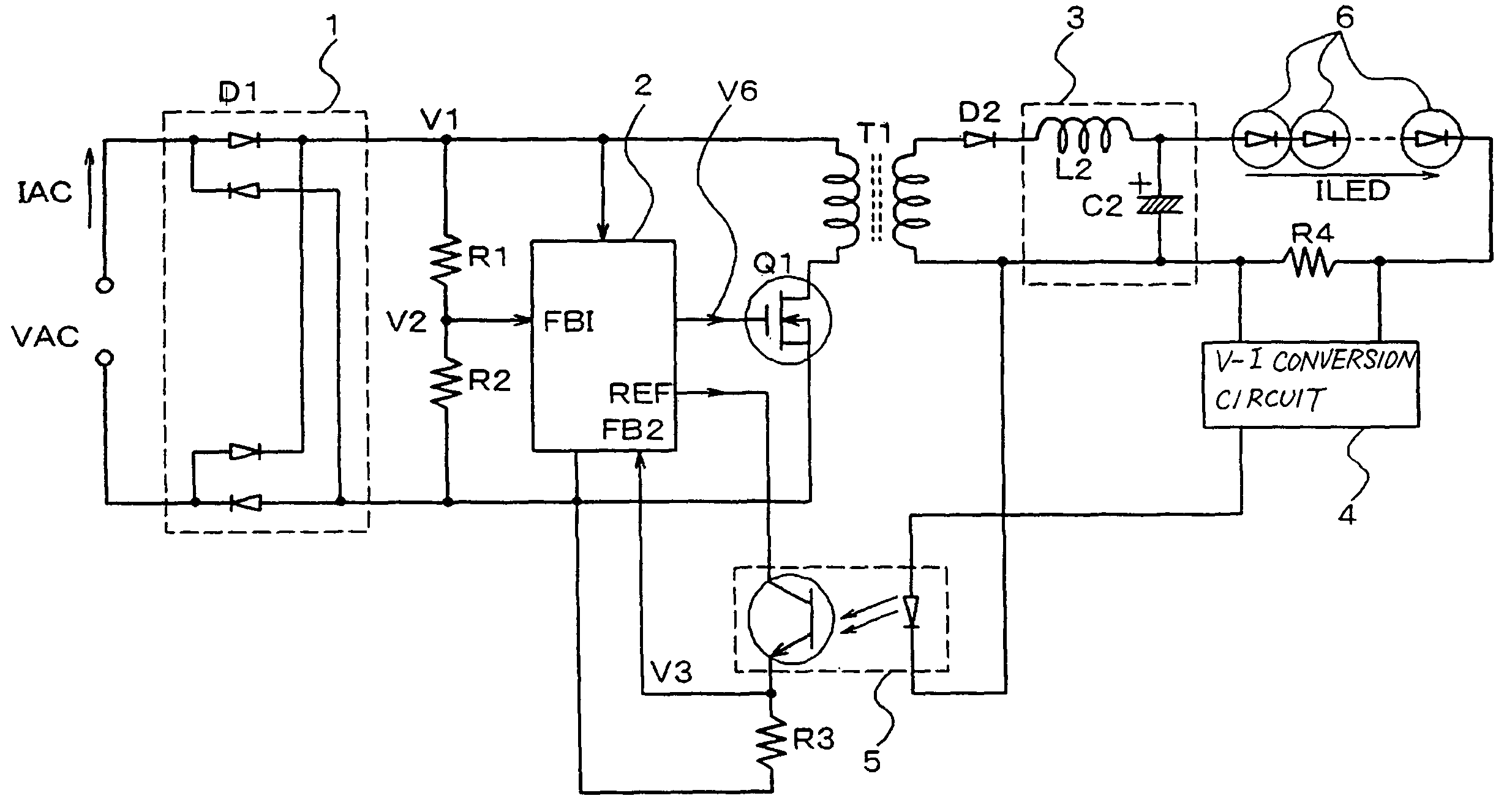
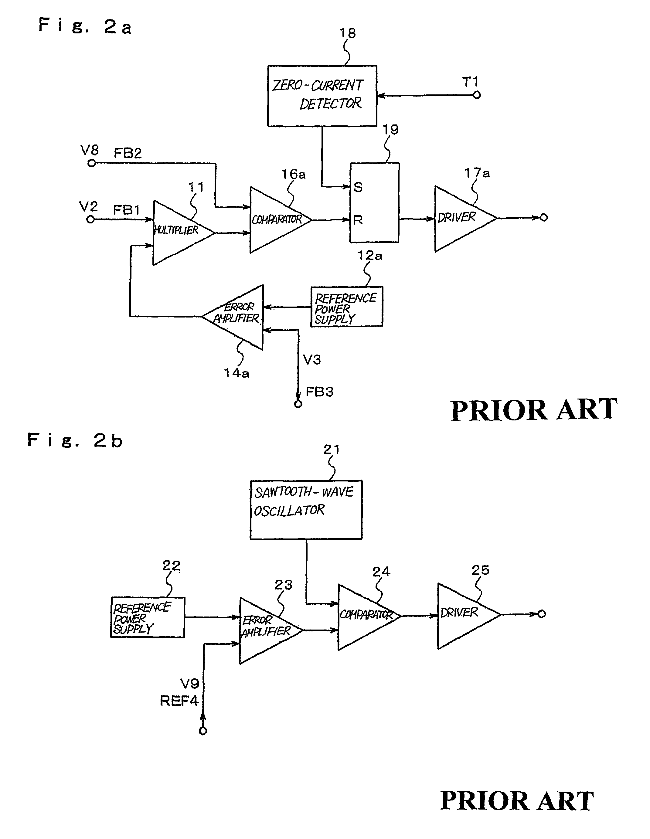
[0084]In the embodiment of FIG. 5, the device for which the details of power-factor control circuit 2 used in FIG. 5 were described was the first working example. FIG. 7 is a block diagram for explaining a working example of power-factor control circuit 2 used in FIG. 5. This power-factor control circuit 2 is made up from: multiplier 11, reference power supply 12, voltage divider 13, error amplifier 14, sawtooth-wave oscillator 15, comparator 16, and driver 17. In this working example, power-factor control circuit 2 compares the detected output of the load current with a prescribed reference value in error amplifier 14 and amplifies this error; multiplies this amplified output with the output of a rectifier in multiplier 11 circuit, compares this multiplied output with a prescribed high-frequency signal in comparator 16, and then drives switch element Q1 by this comparison output.

[0085]Explanation next regards the details of the operation of the power supply circuit according to the...

second working example

[0090]In the first working example of FIG. 5, a FET was shown as switch element Q1, and photocoupler 5 that incorporates an LED and phototransistor was shown as the transmission element of the feedback signal. As another working example, a switch element such as a transistor or IGBT (Insulated-Gate Bipolar Transistor) can also be applied as switch element Q1. Alternatively, if a light-emitting device and a photodetection element can be electrically insulated and signals can be transmitted, the light-emitting device and photodetection element can be applied in place of a photocoupler regardless of the type of light-emitting device and photodetection element. In the working example of FIG. 5, the primary side and secondary side are electrically isolated by means of transformer T1 and photocoupler 5. Although this separation prioritizes ease-of-use, this separation is not an indispensable element for realizing the functions of the present working example.

[0091]According to the configur...


PUM


Abstract

In a low-voltage power supply circuit for illumination that rectifies an ac power supply by means of a rectifier circuit, that controls this rectified output by means of a power-factor control circuit, and that supplies a low-voltage power supply for illumination, the power-factor control circuit is composed of a step-down circuit and is further provided with a current-limiting capability.

Description

BACKGROUND OF THE INVENTION[0001]1. Field of the Invention[0002]The present invention relates to a low-voltage power supply circuit for illumination, an illumination device, and a low-voltage power supply output method for illumination, and more particularly to a low-voltage power supply circuit for illumination, an illumination device, and a low-voltage power supply output method for illumination that uses a delighted light source such as an organic EL or LED.[0003]2. Description of the Related Art[0004]The development of high-luminance LEDs and organic ELs is currently progressing and these devices will soon find use for the purpose of illumination. Although high-luminance LEDs and organic ELs still lack the luminous efficacy of fluorescent lamps, they are said to offer smaller size, thinner construction, and longer life, and above all, enable elimination of the use of mercury, and therefore hold promise as a light source for illumination.[0005]Both high-luminance LEDs and organic...

Claims


Application Information

Patent Timeline
Patent Type & Authority Patents(United States)
IPC IPC(8): G05F1/00H01L33/00H01L51/50H05B44/00H02M3/28H02M7/12H05B37/02H05B41/282
CPCH05B33/0815H05B45/382H05B45/375
Inventor TATSUMI, NAOKI
Owner NEC LIGHTING
Why Eureka
Try Eureka