Nonlinear distortion compensating device

a compensating device and distortion technology, applied in the field of nonlinear distortion compensating devices, can solve the problems of not meeting the performance requirements of the relay device discussed, the technique is not suitable for the relay device, and the pre-distortion technique tends to have a greater delay, so as to achieve power-saving distortion compensation

Active Publication Date: 2007-10-09
PANASONIC INTELLECTUAL PROPERTY CORP OF AMERICA
View PDF17 Cites 7 Cited by
  • Summary
  • Abstract
  • Description
  • Claims
  • Application Information

AI Technical Summary

Benefits of technology

[0014]Another aspect of the present invention is to separate an input signal into plural signals in response to the frequency as necessary, estimate an distortio

Problems solved by technology

However, a conventional pre-distortion technique tends to have a greater delay because it uses a base-band signal as a reference signal, so that this technique does not suit for relay de

Method used


Image

  • Nonlinear distortion compensating device
  • Nonlinear distortion compensating device
  • Nonlinear distortion compensating device

Examples


first exemplary embodiment

1. First Exemplary Embodiment

[0035]The present invention is applied to the digital TV broadcasting communication system. This case is demonstrated hereinafter with reference to accompanying drawings.

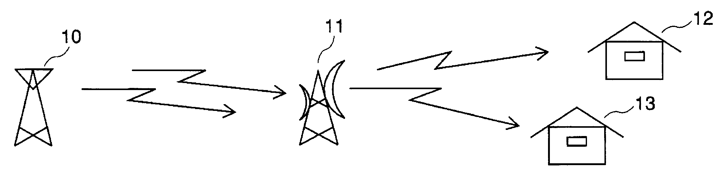
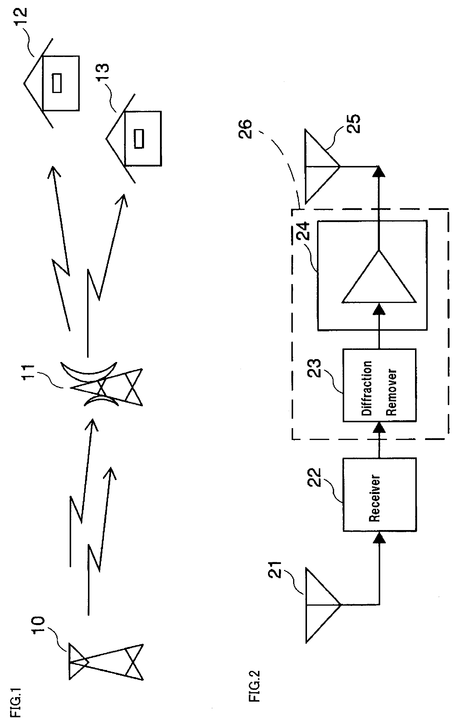
[0036]A basic structure of the digital TV broadcasting communication system is shown in FIG. 1, where transmitter station 10 transmits a signal to receiver stations 12, 13 via relay station 11.

[0037]FIG. 2 shows a schematic structure of relay station 11 to which the present invention is applied. The broadcasting signal transmitted from broadcasting station 10 is received by receiver 22 through antenna 21 in relay station 11. Parts of the received signal is sometimes diffracted to receiving section 22 via a space and mixes with an input signal. This diffracted component is removed by diffraction remover 23, and then distortion compensator 24 compensates the signal for distortion of phase and amplitude. The signal is then amplified before it is output from antenna 25. Transmitter 26 of rel...

second exemplary embodiment

2. Second Exemplary Embodiment

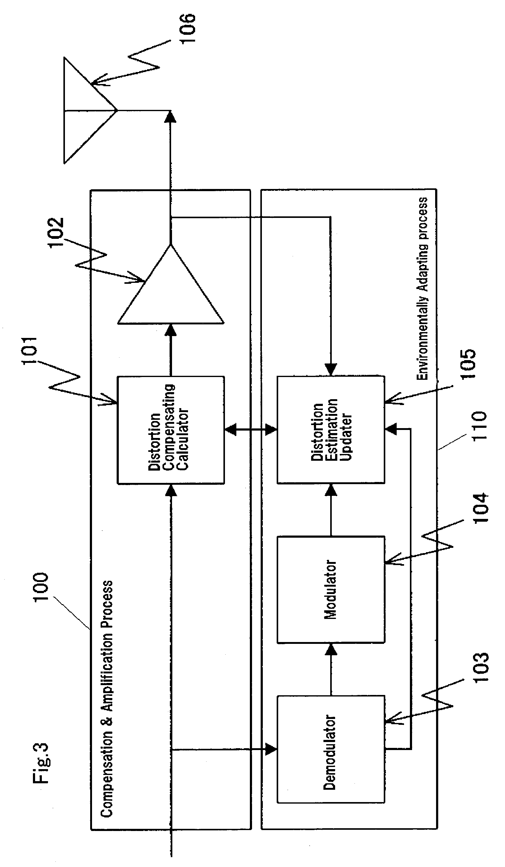
[0083]In addition to the contents described in the first embodiment, an input signal is undergone demodulation and detection, and the signal re-modulated is used as a reference signal in this second embodiment. Only the differences from the first embodiment are described hereinafter with reference to FIG. 3.

[0084]Demodulator 103 demodulates, detects and then converts an input signal into digital data. Parts of the results of the demodulation and detection are supplied to distortion estimating updater 105. Modulator 104 re-modulates the signal based on the digital data converted as well as following the same modulating method and the same frequency as those of the input signal, and outputs the reference signal. Distortion estimating updater 105 calculates a distortion component produced by amplifier 102 based on the results of the demodulation and detection, the reference signal, and a feedback signal from amplifier 102, and outputs a distortion compensa...

third exemplary embodiment

3. Third Exemplary Embodiment

[0102]Another distortion compensator is prepared before the distortion compensating calculator described in the first embodiment, so that a more accurate distortion compensating device is obtainable. This is described in this third embodiment.

[0103]A nonlinear distortion compensating device shown in FIG. 11 comprises the following elements:[0104]propagation-distortion compensator 1150 for receiving an input signal, and outputting a propagation distortion compensating signal that compensates for a distortion produced in the propagation path;[0105]element-distortion compensator 1151 for receiving the propagation distortion compensating signal, and outputting an element distortion compensating signal that estimates and cancels a distortion component of amplifier 102;[0106]amplifier 102 for receiving the element distortion compensating signal, and outputting an amplified signal; and[0107]antenna 106 for radiating the output signal.

[0108]Element-distortion co...


PUM


Abstract

A nonlinear distortion compensating device splits its operation into two processes. One is a compensation & amplification process for providing a receipt signal with a distortion compensating calculation and amplification before outputting the signal with phase and amplitude compensated. The other is an environmentally adapting process for modulating the signal demodulated from the input signal. Then in this process, a distortion estimating updater estimates a distortion amount using the modulated signal and a feed back signal of parts of the output supplied from the distortion compensating calculator, and updates a distortion compensating coefficient stored in the distortion compensating calculator.

Description

FIELD OF THE INVENTION[0001]The present invention relates to a nonlinear distortion compensating device which compensates a transmitting system of digital radio communication for distortion, and it also relates to a transmitting apparatus using the same device.BACKGROUND OF THE INVENTION[0002]The technique of digital radio communication has been developed, and sophisticated modulating methods are adopted in the radio communication. For instance, the digital TV broadcasting adopts the following system in order to expand a service area: as shown in FIG. 1, a signal transmitted from transmitter station 10 is received by receiver stations 12, 13 via relay station 11. Relay station 11 is formed of an amplifier and an antenna in order to receive an RF signal from transmitter station 10 and amplify it before redelivering the RF signal at the same or different frequency. Such relay station 11 is strongly required to be highly efficient between receiving and redelivering the signal in additi...

Claims


Application Information

Patent Timeline
IPC IPC(8): H04K1/02H03D1/04H04B1/04H04L25/03H03F1/32H04L27/36
CPCH03F1/3247H03F1/3282H04L27/368H04B7/15535H04B2001/0433H03F2201/3233H03F1/34H03F3/24
Inventor ORIHASHI, MASAYUKIMURAKAMI, YUTAKATAKABAYASHI, SHINICHIRMATSUOKA, AKIHIKO
Owner PANASONIC INTELLECTUAL PROPERTY CORP OF AMERICA
Why Eureka
Try Eureka