Readout controlling apparatus, reproducing apparatus, recording apparatus, and readout controlling method

Inactive Publication Date: 2007-10-09
SONY CORP
View PDF33 Cites 10 Cited by
  • Summary
  • Abstract
  • Description
  • Claims
  • Application Information

AI Technical Summary

Benefits of technology

[0029]According to a second aspect of the invention, there is a player, comprising a reproducing means for reproducing data from a recording medium; an error correcting means for correcting error of the reproduced data; an error rate calculating means for calculating an error rate of the error correction; and a control means for controlling reproduction conditions of the reproducing means so that the error rate becomes small.
[0030]According to a third aspect of the present invention, there is provided a recorder, comprising a recording means for recording data on a recording medium; a reading means for reading the recorded data; an err

Problems solved by technology

Accordingly, when the playback condition of a DVD is poor and more than a predetermined number of bytes include error, there is a disadvantage that there are bytes unable to be corrected for error and therefore quality of

Method used


Image

  • Readout controlling apparatus, reproducing apparatus, recording apparatus, and readout controlling method
  • Readout controlling apparatus, reproducing apparatus, recording apparatus, and readout controlling method
  • Readout controlling apparatus, reproducing apparatus, recording apparatus, and readout controlling method

Examples


first embodiment

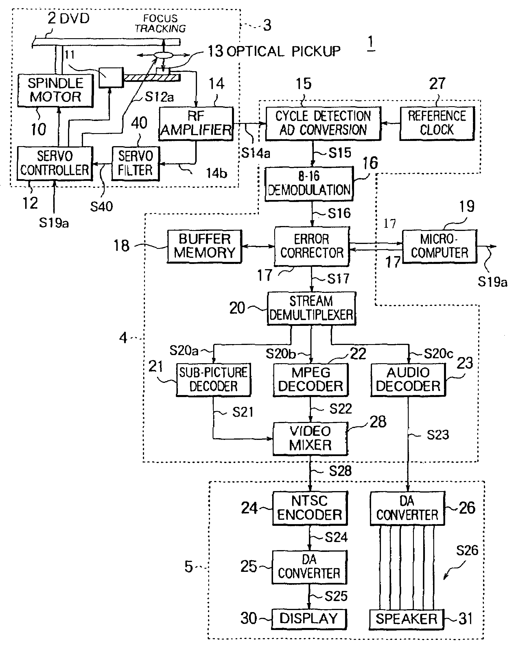
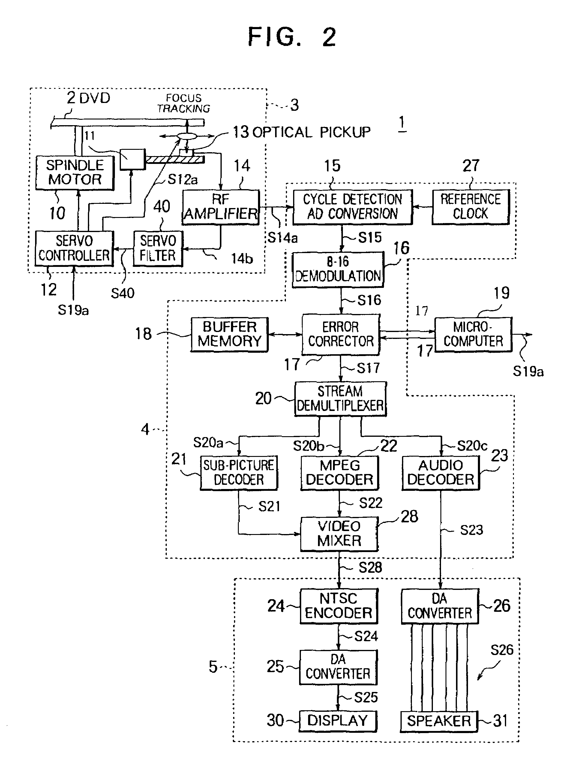
[0049]FIG. 2 is a view of the configuration of a DVD player according to a first embodiment of the present invention.

[0050]As shown in FIG. 2, the DVD player 1 comprises a reading system 3, a decoding system 4, an output system 5, and a microcomputer 19.

[0051]The DVD player 1 calculates an error rate at the microcomputer 19 based on error correction results in an error corrector 17 and controls a focus servomechanism in an optical pickup 13 based on the error rate.

[0052][Reading System 3]

[0053]The reading system 3 comprises a spindle motor 10, a feed motor 11, a servo controller 12, the optical pickup 13, an RF amplifier 14, and a servo filter 40.

[0054]The servo controller 12 controls the spindle motor 10, feed motor 11, and optical pickup 13.

[0055]For example, the servo controller 12 generates a focus servo signal based on a parameter instruction signal S19a from the microcomputer 19 and a focus error signal S40 from a servo filter 40 and outputs the generated focus servo signal S1...

second embodiment

[0189]FIG. 8 is a view of the configuration of a DVD player 201 according to a second embodiment of the present invention.

[0190]In FIG. 8, components having the same reference numerals as in FIG. 2 are the same as those explained in the first embodiment.

[0191]Namely, the DVD player 201 is characterized by its servo controller 212, error corrector 217, and microcomputer 219.

[0192][Servo Controller 212]

[0193]The servo controller 211 controls the spindle motor 10, feed motor 11, and optical pickup 13.

[0194]In the present embodiment, the servo controller 211 controls the speed of the spindle motor 10 based on a spindle speed change instruction signal S219a from the microcomputer 19.

[0195][Error Corrector 217]

[0196]FIG. 9 is a view of the configuration of the error corrector 217.

[0197]In FIG. 9, components having the same reference numerals as in FIG. 3 are the same as in the error corrector 17 explained in the first embodiment.

[0198]As shown in FIG. 9, the error corrector 217 comprises ...

third embodiment

[0238]FIG. 12 is a view of the configuration of a DVD player 301 according to a third embodiment of the present invention.

[0239]In FIG. 12, components having the same reference numerals as in FIG. 2 and FIG. 8 are the same as those in the first and second embodiments.

[0240]Namely, the DVD player 301 is characterized in its servo filter 340 and microcomputer 319.

[0241][Servo Filter 340]

[0242]The servo filter 340 filters the focus error signal S14b from the RF amplifier 14 by predetermined filter characteristics and outputs the filtered focus error signal S34c to the servo controller 12.

[0243]Note that, for example, a digital filter of a DSP is used as the servo filter 340. One set of filter characteristics is selected from filter characteristics for scratched disks and filter characteristics for scratch-free disks in accordance with a filter characteristic instruction signal S319a from the microcomputer 319 to filter the focus error signal, tracking error signal, etc. from the RF amp...


PUM


Abstract

A readout controlling apparatus for controlling reading conditions at the time of reading data coded in units of predetermined code blocks from a recording medium capable of performing error correction at a high reliability even when the playback conditions are poor by calculating an error rate using the number of bytes for which outer code error correction has been completed etc. in the error correction in an error corrector and controlling the reading conditions so that the error rate becomes small.

Description

BACKGROUND OF THE INVENTION[0001]1. Field of the Invention[0002]The present invention relates to a readout controlling apparatus, player, and recorder of a digital disk or other recording media and a readout controlling method.[0003]2. Description of the Related Art[0004]When playing back a digital versatile disk (DVD), a DVD player etc. converts an analog signal read from the DVD to a digital signal and applies 8 to 16 demodulation to the digital signal. It then stores one error correcting code (ECC) block's worth of the digital signal obtained by the 8 to 16 demodulation in a buffer memory, then reads this out, corrects its errors, and decodes the error corrected digital signal.[0005]Here, the error correction is performed in units of ECC blocks on the digital signal read from the DVD.[0006]FIG. 1 is a view for explaining the format of an ECC block.[0007]BM,N (0≦M≦192, 0≦N≦171) shown in FIG. 1 is information data composed of 16 sectors each comprised by 172 bytes times 12 rows.[00...

Claims


Application Information

Patent Timeline
IPC IPC(8): G06F11/00G11B7/004G11B20/18G11B5/09
CPCG11B20/1803G11B2020/1853
Inventor HAYASHI, TSUNEOYASUDA, KAZUHIRO
Owner SONY CORP
Why Eureka
Try Eureka