Acceleration sensor

a triaxial acceleration and sensor technology, applied in the direction of acceleration measurement in multiple dimensions, acceleration measurement using interia forces, instruments, etc., can solve the problem of not considering the power saving kind, and achieve the effect of natural drop in sensitivity, power saving, and easy reduction of output difference between the x axis and the z axis

Inactive Publication Date: 2007-10-16
LAPIS SEMICON CO LTD
View PDF2 Cites 7 Cited by
  • Summary
  • Abstract
  • Description
  • Claims
  • Application Information

AI Technical Summary

Benefits of technology

[0019]According to the present invention, the length L2 of each Z-axis piezo-resistor is longer than the length L1 of the X-axis piezo-resistor. The length L1 area is the largest distortion area. Thus, the Z-axis piezo-resistor inevitably includes a smaller-distortion area, and its sensitivity naturally drops. Accordingly, the output difference between the X axis and the Z axis can be easily decreased. Also the length L2 of each Z-axis piezo-resistor is longer than the length L1 of each X-axis piezo-resistor, so that the resistance of the Z-axis piezo-resistor is higher than that of the X-axis piezo-resistor. Therefore, when a constant voltage is applied to the acceleration sensor for driving, the current that flows through the Z-axis piezo-resistors decreases and power can be saved in the Z-axis piezo-resistors. This contributes to power saving of the entire acceleration sensor.
[0020]When the length L2 of the Z-axis piezo-resistors is a simple extension of the length L1, i.e., when the length L2 includes the length L1 entirely, and is longer than the length L1, the determination of the length L2 becomes easier because the value of the length L1 is usually already known. The calculation of the length L2 which includes the length L1 is easy.

Problems solved by technology

When the acceleration sensor is mounted on a portable terminal equipment and is driven by battery, it is preferable that the power consumption of the angular velocity sensor is smaller, but in Japanese Patent Kokai No. 2003-279592, this kind of power saving is not considered, and a technically satisfactory angular velocity sensor has not yet been implemented.

Method used


Image

  • Acceleration sensor
  • Acceleration sensor
  • Acceleration sensor

Examples


embodiment 1

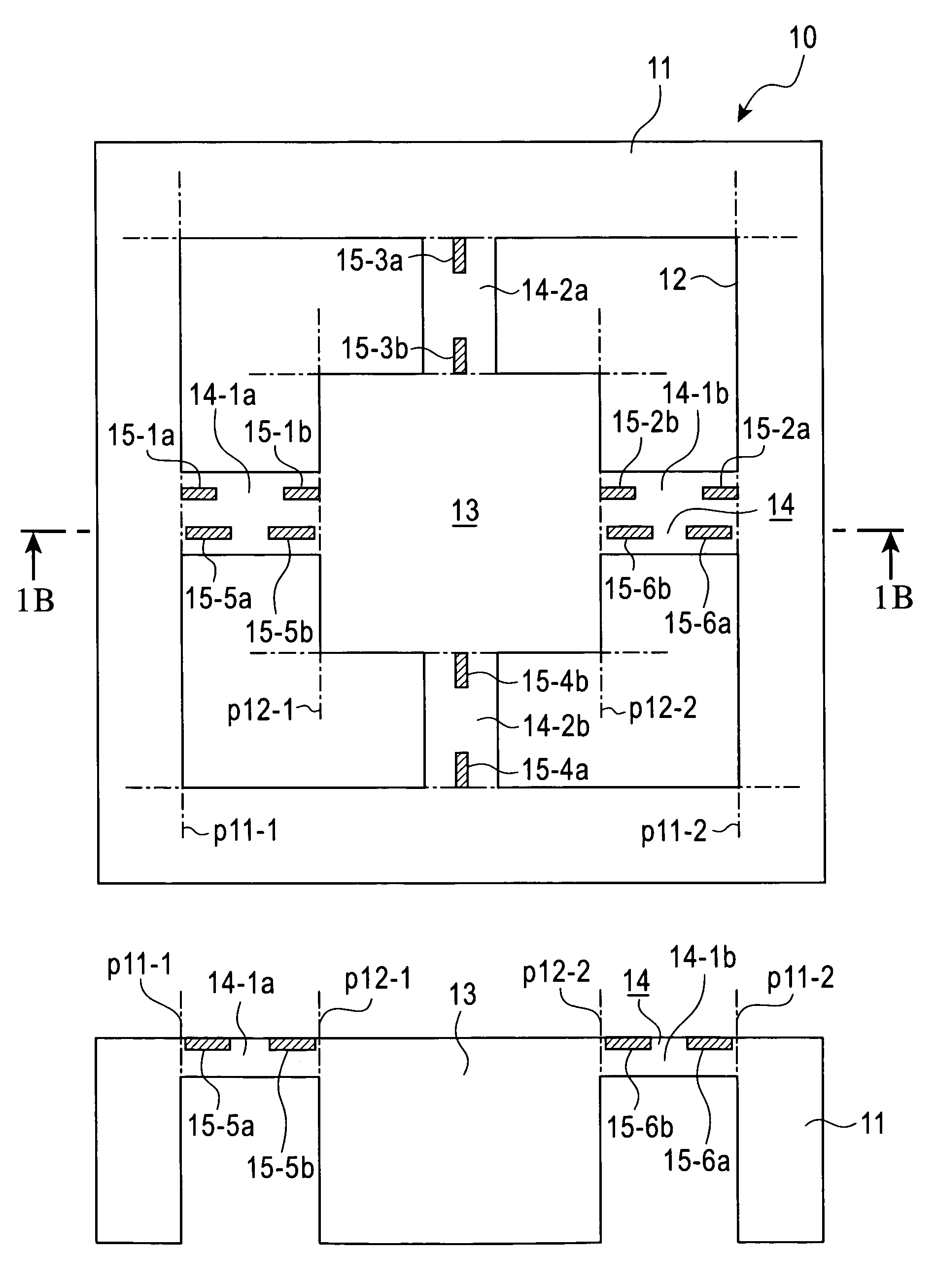
[0030]Referring to FIG. 1A and FIG. 1B, the configuration of the piezo-resistance type triaxial acceleration sensor 10 according to a first embodiment of the present invention will be described.

[0031]This acceleration sensor 10 is made from a silicon mono-crystal substrate, just like a prior art, and has roughly a square frame section 11. At the four corners inside the frame section 11, roughly L-shaped openings 12 are formed penetrating in the Z axis direction, that is a vertical direction to the FIG. 1A drawing sheet. At the inner center of the four openings 12, a cubic mass section 13, which is a thick weight, is disposed. The mass section 13 is flexibly connected to the frame section 11 by the thin beam section 14. The beam section 14 includes two rectangular beam elements 14-1a and 14-1b extending in the X axis direction, which is the width direction of the FIG. 1A drawing sheet, and two rectangular beam elements 14-2a and 14-2b extending in the Y axis direction, which is the h...

embodiment 2

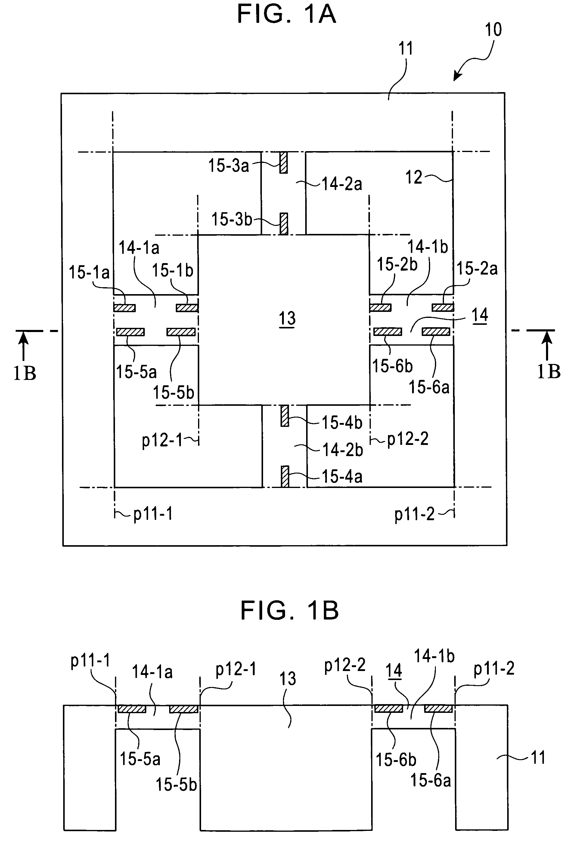
[0047]FIG. 3A and FIG. 3B are enlarged plan views depicting Embodiment 2 of the present invention. FIG. 3A and FIG. 3B are similar to FIG. 2A and FIG. 2B, and illustrate the formation locations and shapes (particularly the lengths L1 and L2) of the piezo-resistors 15-1a, 15-1b to 15-6a, 15-6b which are formed on the beam elements 14-1a, 14-1b, 14-2a and 14-2b shown in FIG. 1A. In FIG. 3A, only the beam element 14-1a is shown to simplify the illustration.

[0048]The primary feature of the present invention lies in that the length L2 of the Z-axis piezo-resistors 15-5a, 15-5b, 15-6a and 15-6b is longer than the length L1 of the X-axis piezo-resistors 15-1a, 15-1b, 15-2a and 15-2b so as to drop the sensitivity of the Z-axis piezo-resistors. In Embodiment 2, each Z-axis piezo-resistor 15-5a, 15-5b, 15-6a and 15-6b includes the length L1 of the corresponding X-axis piezo-resistor 15-1a, 15-1b, 15-2a and 15-2b entirely and also includes a smaller-distortion area, to drop the sensitivity.

[00...

embodiment 3

[0054]The present invention is not limited to the above described and illustrated embodiments, and can be modified in various ways. One example of such modifications will be described as Embodiment 3.

[0055]The shape of the acceleration sensor 10 is not limited to a square. A rectangle or a circle is acceptable. The shapes and the numbers of the weight section 13, the beam elements 14 which support the weight section 13, and the piezo-resistors 15-1a, 15-1b to 15-6a, 15-6b formed on the beam elements are also not limited to the above-described or illustrated shapes and numbers.


PUM


Abstract

The piezo-resistance type triaxial acceleration sensor includes a frame section, a mass section disposed in the frame section, beam elements which flexibly support the mass section, and piezo-resistors for the X, Y and Z axes formed on the beam elements. The length of the Z-axis piezo-resistors is longer than the length of the X-axis piezo-resistors and the Y-axis piezo-resistors, so as to decrease the sensitivity.

Description

BACKGROUND OF THE INVENTION[0001]1. Field of the Invention[0002]The present invention relates to a piezo-resistance type triaxial acceleration sensor used for portable terminal equipment and other similar small devices for detecting acceleration in three axis directions (X, Y and Z axis directions), and more particularly to a technology for reducing the output difference among the three axes (X, Y and Z axes) so as to save power.[0003]2. Description of the Related Art[0004]Conventional technology on an acceleration sensor for decreasing the output difference among the three axes (X, Y and Z axes) is, for example, disclosed in Japanese Patent Application Kokai (Application Laid-Open) No. 2003-279592.[0005]FIG. 4A and FIG. 4B of the accompanying drawings depict the conventional piezo-resistance type triaxial acceleration sensor disclosed in Japanese Patent Application Kokai No. 2003-279592. FIG. 4A is a plan view and FIG. 4B is a cross-sectional view taken along the line 4B-4B in FIG....

Claims


Application Information

Patent Timeline
Patent Type & Authority Patents(United States)
IPC IPC(8): G01P15/12G01P15/18H01L29/84
CPCG01P15/18G01P15/123G01P2015/084G01P15/09
Inventor MORI, HIRONARI
Owner LAPIS SEMICON CO LTD
Why Eureka
Try Eureka