
Method and system of diesel engine setpoint compensation for transient operation of a heavy duty diesel engine

Inactive Publication Date: 2007-10-16
DETROIT DIESEL CORP
View PDF32 Cites 32 Cited by
  • Summary
  • Abstract
  • Description
  • Claims
  • Application Information

AI Technical Summary

Benefits of technology

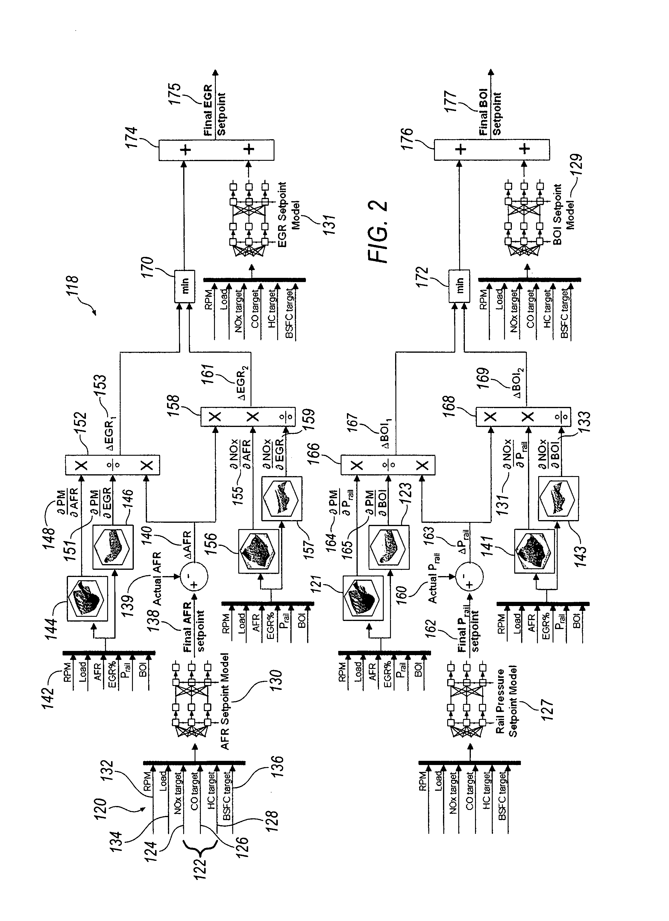
[0009]The present invention is directed in one embodiment to a method to improve transient emission control in an electronically controlled heavy duty diesel engine equipped with a fuel system and an air system having an EGR circuit, and a memory within an Engine Control Module (ECM). The method comprises determining a required transient air fuel ratio; determining a change in air fuel ratio(ΔAFR);determining a change in EGR setpoint (ΔEGR) to compensate for air system response; determining a transient EGR setpoint; determining a final EGR setpoint; determining a required transient fuel system pressure setpoint; determining a change in fuel system pressure comparing; determining a change in beginning of injection (ΔBOI); determining a transient beginning of injection setpoint; determining a final beginning of injection setpoint; implementing the final EGR setpoint to compensate for the air system reaction time during transient engine operation and implementing the final BOI to compensate for the fuel system reaction times during transient engine operation to improve engine operation and reduce emissions.
[0010]The present invention further relates to a method to improve transient emission control in an electronically controlled heavy duty diesel engine equipped with a common rail fuel system and an air system having an EGR, and a memory within a Engine Control Module (ECM), comprising, estimating a required transient air-fuel ratio setpoint from an air-fuel ratio setpoint model using engine emission targets and fuel economy targets; comparing said required transient air-fuel ratio setpoint with an actual air fuel ratio to compute a difference between the required transient air fuel ratio and the actual air fuel ratio as Δ Air Fuel Ratio (ΔAFR); calculating a partial derivative of at least one target engine emission with respect to air fuel ratio (Δ target emission / ΔAFR); calculating a partial derivative of at least one target engine emission with respect to EGR (Δ target emission / Δ EGR); multiplying ΔAFR by the rate of change of target emission with respect to AFR (Δ target emission / Δ AFR) and dividing said sum by the rate of change of the target emission with respect to EGR(Δ target emission / Δ EGR) to calculate the change in EGR (ΔEGR) setpoint necessary to compensate for the air response; estimating a transient EGR setpoint from an EGR setpoint model using engine emission targets and fuel economy targets; calculating a final EGR setpoint by adding the ΔEGR and the transient EGR setpoint; estimating a required transient common rail pressure setpoint from a common rail pressure setpoint model using engine emission targets and fuel economy targets; comparing said transient common rail pressure with an actual common rail pressure and computing a difference between the transient common rail pressure and the actual common rail pressure as ΔPrail; calculating a partial derivative of at least one target engine emission with respect to common rail pressure (Δ target emission / ΔPrail); calculating a partial derivative of at least one target engine emission with respect to beginning of injection (Δ target engine emission / Δ BOI); multiplying the Δ Prail by the rate of change of target emission with respect to rail pressure (Δ target emission / Δ Prail) and dividing said sum by the rate of change of target emission with respect to BOI (Δtarget emission / Δ BOI) to calculate the change in beginning of injection (ΔBOI); estimating a transient beginning of injection setpoint from a beginning of injection setpoint model using engine emission targets and fuel economy targets; calculating a final beginning of injection setpoint (Final BOI) by adding the ΔBOI and the transient beginning of injection setpoint; implementing the final EGR setpoint to compensate for the air system reaction time during transient engine operation and implementing the final BOI to compensate for the fuel system reaction times during transient engine operation to improve engine operation and reduce emissions.

Problems solved by technology

During transient operation of the engine, it is difficult to control engine emissions.

Method used


Image

  • Method and system of diesel engine setpoint compensation for transient operation of a heavy duty diesel engine
  • Method and system of diesel engine setpoint compensation for transient operation of a heavy duty diesel engine
  • Method and system of diesel engine setpoint compensation for transient operation of a heavy duty diesel engine

Examples


Embodiment Construction

)

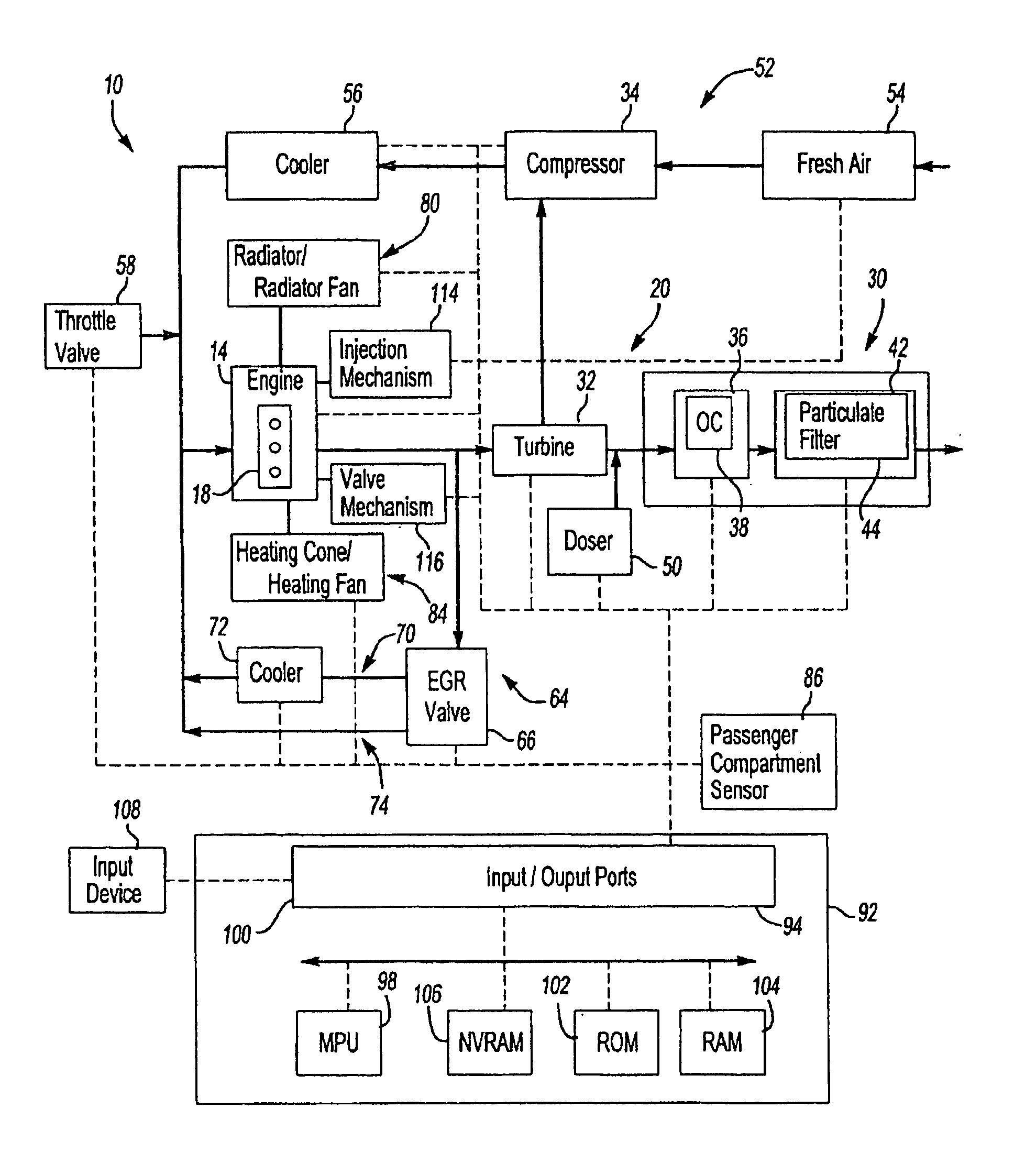
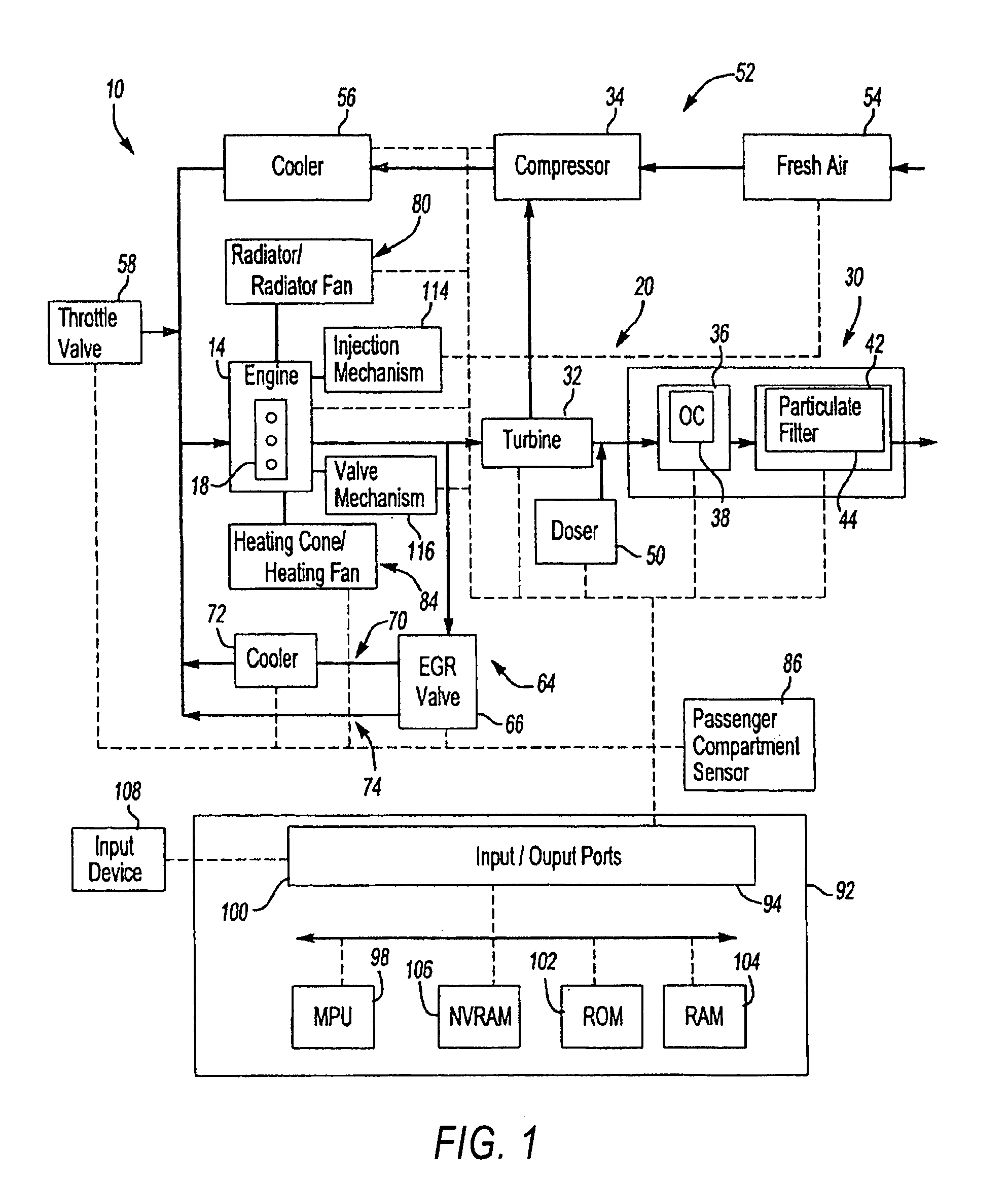
[0011]FIG. 1 illustrates a vehicle powertrain system 10 in accordance with one non-limiting aspect of the present invention. The system 10 may provide power for driving any number of vehicles, including on-highway trucks, construction equipment, marine vessels, stationary generators, automobiles, trucks, tractor-trailers, boats, recreational vehicle, light and heavy-duty work vehicles, and the like.

[0012]The system 10 may be referred to as an internal combustion driven system wherein fuels, such as gasoline and diesel fuels, are burned in a combustion process to provide power, such as with a compression ignition engine 14. The engine 14 may be a diesel engine that includes a number of cylinders 18 into which fuel and air are injected for ignition as one skilled in the art will appreciate. The engine 14 may be a multi-cylinder compression ignition internal combustion engine, such as a 4, 6, 8, 12, 16, or 24 cylinder diesel engines, for example.

[0013]Exhaust gases generated by the en...


PUM


Abstract

Method for controlling and improving the transient emissions of an electronically controlled heavy duty diesel engine having an ECM with memory, a turbocharger and an EGR system.

Description

BACKGROUND OF THE INVENTION[0001]1. Field of the Invention[0002]The present invention is directed to a method and system of diesel engine setpoint compensation for transient operation of a heavy duty diesel engine.[0003]2. Description of the Related Art[0004]Sun et al, U.S. Pat. No. 6,866,030 is directed to a method for controlling a compression ignition internal combustion engine exhaust recirculation (EGR) system having an EGR valve and an actuator. The method includes continuously monitoring at least one engine parameter in real time, and continuously adjusting as EGR valve position using a control signal in real time in response to the at least one parameter and in response to at least one delay, wherein one of the at least one delays corresponds to as EGR actuator delay.[0005]Sun, U.S. Pat. No. 7,063,076 is directed to a method of smoke limiting of an engine. The method may include determining a minimum air / fuel (AFR) ratio and fuel limiting as a function thereof. The method ma...

Claims


Application Information

Patent Timeline
IPC IPC(8): F02M1/00B60T7/12
CPCF01N13/0097F01N3/103F02D41/005F02D41/107F02D41/1462F02D41/1467F01N3/0253F02B3/06F02B37/00F02B37/24F02D13/04F02D41/1405F02M25/0707F02M25/0728Y02T10/47F01N3/035F02M26/05F02M26/25Y02T10/40
Inventor ALLAIN, MARC CHRISTIANSUN, MIN
Owner DETROIT DIESEL CORP
Learn More