VTOL/STOL ducted propeller aircraft

a technology of ducted propeller aircraft and vtol, which is applied in the direction of vertical landing/take-off aircraft, aircraft navigation control, transportation and packaging, etc., can solve the problems of increasing weight and lowering performance, and achieve the effect of preventing vibration or flutter

Inactive Publication Date: 2007-10-16
MELKUTI ATTILA
View PDF5 Cites 15 Cited by
  • Summary
  • Abstract
  • Description
  • Claims
  • Application Information

AI Technical Summary

Benefits of technology

[0016]In the conventional configuration, roll, pitch, and yaw are controlled through conventional aerodynamic surface adjustments of ailerons, rudders, and elevator. The aircraft of this invention is also equipped with louvers positioned below the propeller. When the S / VTOL aircraft is tilted forward for horizontal flight, the thrust already has a significant horizontal component, but tilting or pivoting these louvers directs the thrust created by the propeller directed backward horizontally for high speed cruise. These louvers are designed to be flexible only in one direction, so when they reach the maximum tilting range, they are stopped by a stopping block, so they can be bent to the point where they form a nice arch for smooth airflow in a horizontal direction. Pressing the louvers against the stopping blocks will also prevent vibration or flutter.
[0017]The entire aircraft of this invention is shaped in a way so that the airflow can smoothly enter the ducted propeller assembly during horizontal and vertical flight and also exit the duct smoothly. This is achieved by bridging the airfoil shaped fuselage over the ducted propeller assembly, and by shaping the frontal area of the duct and the aft extension as an airfoil in a way to assume a horizontal position in horizontal flight.

Problems solved by technology

They may involve:1) Cumbersome, and therefore heavy, mechanisms for moving massive structures such as wings or ducted fan assemblies; or2) Sacrificing aerodynamic smoothness, thereby creating unacceptable drag; or3) Multiple power plants or complex drive trains, thus increasing weight and lowering performance.

Method used


Image

  • VTOL/STOL ducted propeller aircraft
  • VTOL/STOL ducted propeller aircraft
  • VTOL/STOL ducted propeller aircraft

Examples


Embodiment Construction

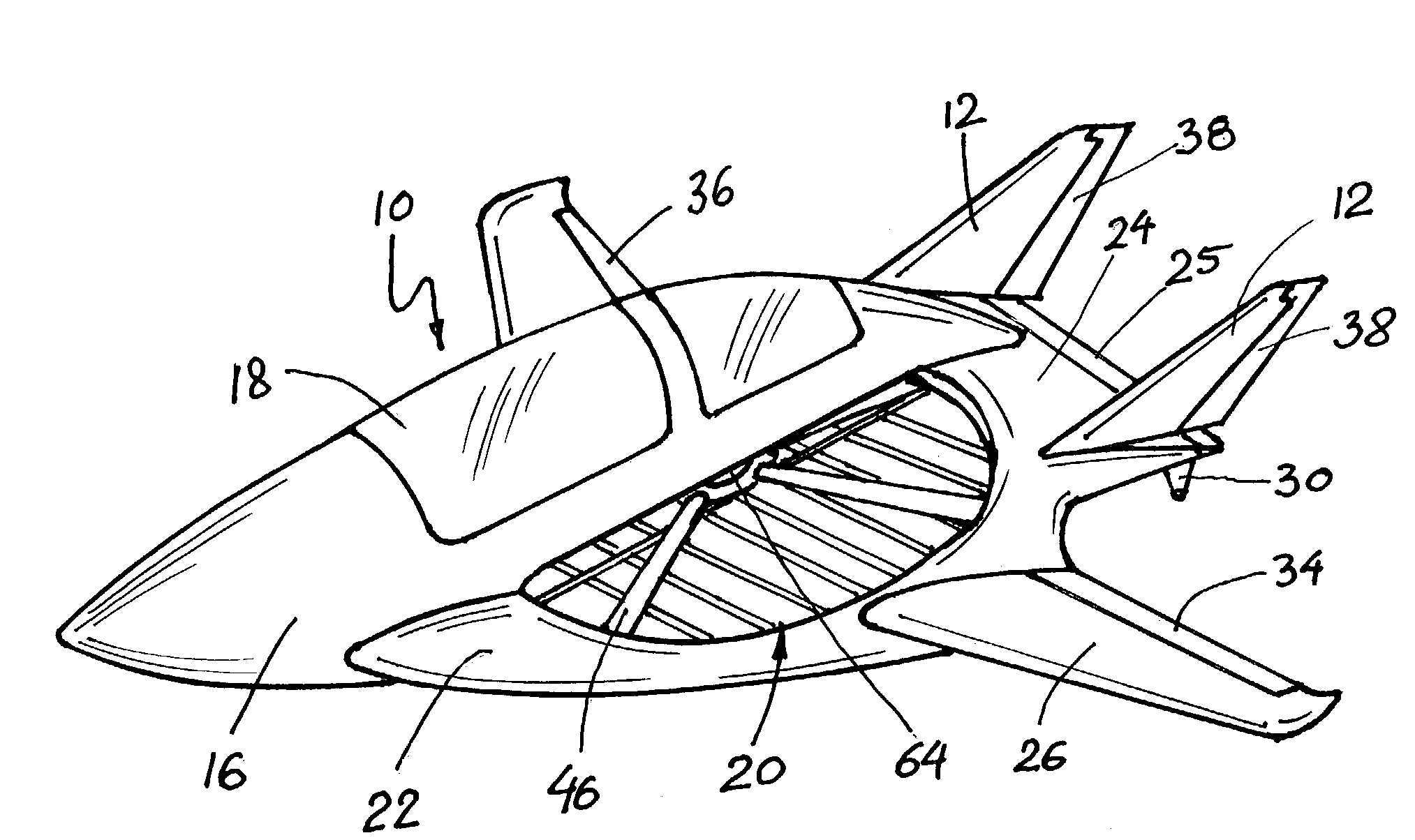
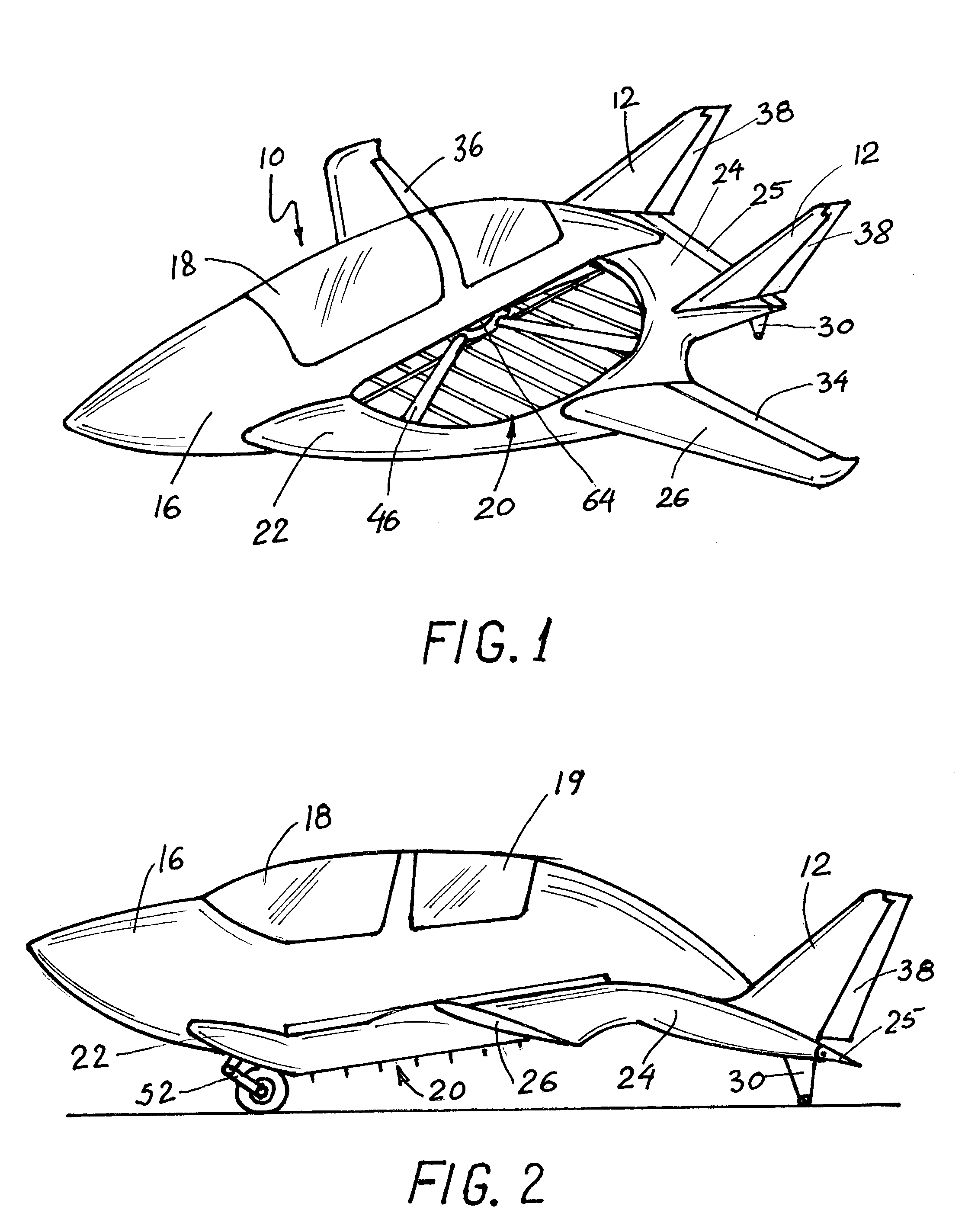
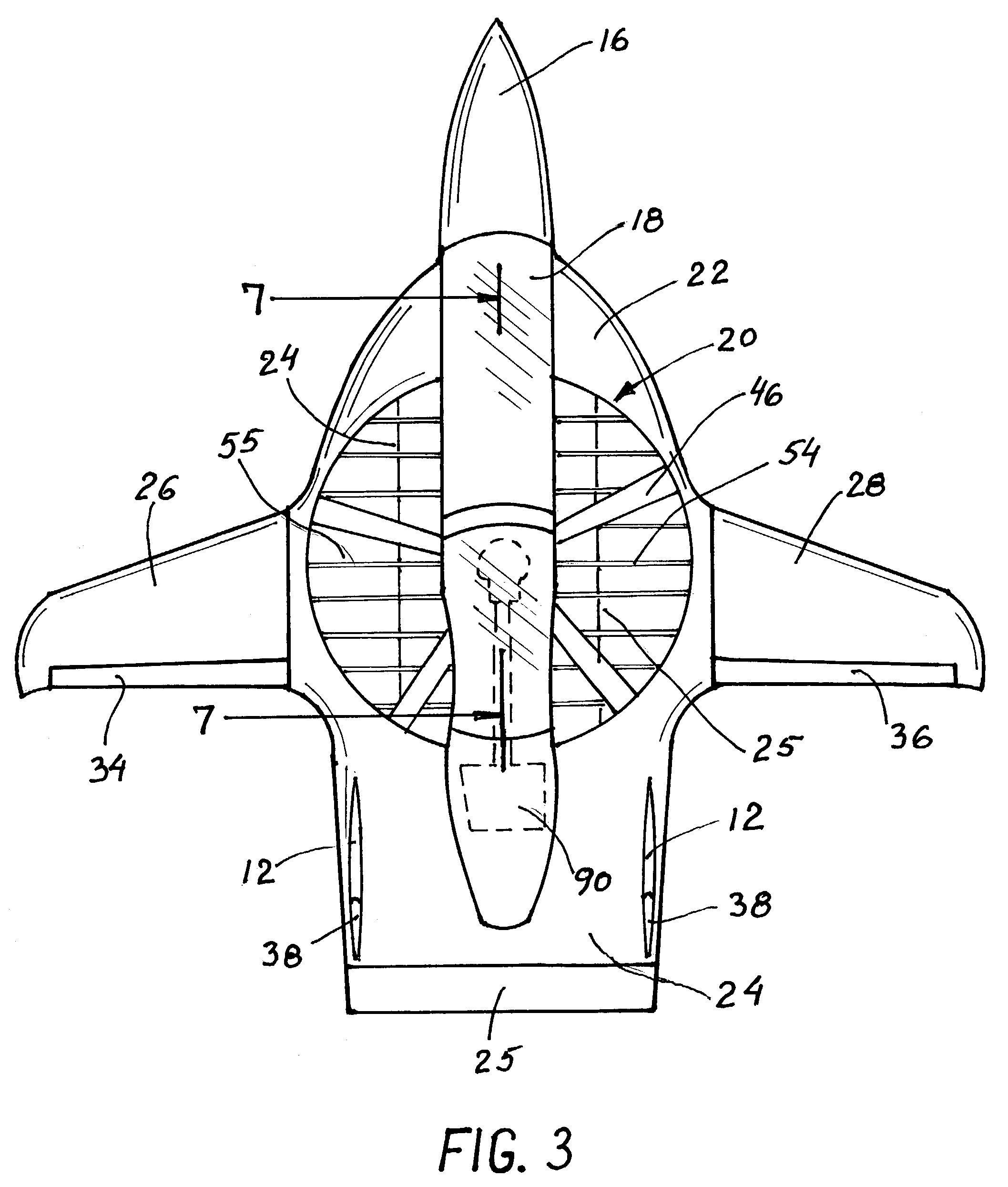
[0031]Referring to the drawings, and particularly the FIGS. 1 through 5, the aircraft 10 of the invention is illustrated. As used herein the term aircraft is meant to include any airborne vehicle. In the preferred embodiment, the aircraft 10 takes the form of a single engine 90 turbo shaft, or rotary (Wankel type) powered aircraft incorporating the fuselage 16 which houses a tandem cockpit with canopy 18 and 19. The fuselage 16 (and the cockpit) bridges over a ducted propeller assembly 20. The fuselage 16, or particularly the cockpit section, bridges directly over the axis of the propeller and tapers to a minimum cross-section to maximize air flow through the duct.

[0032]The ducted propeller assembly 20 incorporates a forward lifting airfoil shaped surface 22 and extends through an aft extension, which forms the tail lifting surface 24 which mounts an elevator 25 and a pair of vertical tail surfaces which incorporates a pair of rudders 38.

[0033]Span wise the forward lifting surface 2...


PUM


Abstract

The aircraft incorporates a single ducted propeller. The fuselage Bridges over the ducted propeller assembly, and is shaped in a way that the incoming air can smoothly flow into the propeller area. The duct has an aerodynamically shaped frontal area, and an aft extension, which forms the tail section. The wings are attached to the side of the duct. The ducted propeller assembly also contains louvers, which run span wise, to redirect the outgoing air in horizontal direction. During vertical take-off or landing, the propeller has a horizontal plane of rotation, after take-off the whole craft entirely tilts forward approximately 26 degrees to transition into horizontal wing born flight. During vertical flight, the aircraft is controlled by control louvers installed inside the ducted propeller assembly in the propeller slipstream.

Description

BACKGROUND OF THE INVENTION[0001]The ultimate goal in designing a fixed wing VTOL aircraft is to be able to take off and land vertically and still have a smooth transition to a higher cruise speed and a relatively long range.[0002]It also needs to have a simple and effective way of controlling the aircraft during vertical take off or landing, and in transition to horizontal flight.[0003]My previous patent (U.S. Pat. No. 5,454,531 DUCTED PROPELLER AIRCRAFT) addresses the difficult challenge of vertical or short takeoff or landing in fixed wing aircraft with high speed cruise, with a multiple propeller configuration.[0004]With this present invention, I am simplifying the propulsion system by using only one propeller. With the single propeller this aircraft is more efficient, it is lighter, simpler, and safer. By tilting the whole aircraft forward to produce a horizontal thrust component, and using a single propulsion system, for vertical and horizontal flight, this invention eliminate...

Claims


Application Information

Patent Timeline
Patent Type & Authority Patents(United States)
IPC IPC(8): B64C29/00B64C27/20
CPCB64C29/0025B64C27/20
Inventor MELKUTI, ATTILA J.
Owner MELKUTI ATTILA
Why Eureka
Try Eureka