Single-use lancet device

a single-use, lancet technology, applied in the field of single-use lancets, can solve the problems of reducing unable to properly retract the lancet after firing, and unable to meet the needs of use, so as to achieve the highest quality finished product and reduce the cost of the device

Inactive Publication Date: 2007-10-16
AMBI INC
View PDF7 Cites 110 Cited by
  • Summary
  • Abstract
  • Description
  • Claims
  • Application Information

AI Technical Summary

Benefits of technology

[0009]The configuration of the present invention has advantages not previously described in the prior art. The device is pre-cocked when it is manufactured and therefore makes cocking by the user unnecessary. In molding the bottom half of the case in the preferred embodiment, a small hole in the floor of the case allows a transverse trigger bar to be molded about 2 mm above the floor, in continuity with two vertical uprights. The intact trigger bar is positioned to bear against an abutment on the underside of the needle carrier. The bottom half of the device therefore provides both a channel for movement of the needle carrier and means to hold the carrier in place against the constant pressure from the compressed mainspring.
[0011]The present invention includes an advance in the manufacturing of single-use lancet devices relating to a novel method of cocking and assembly of the device which facilitates manufacturing the lancet either with automation or manually. In this technique to be described, a disposable tailpiece at the lower end of the lancet carrier allows the spring to be dropped onto the back end of the carrier and compressed before the needle carrier is placed inside the clam shell body.
[0012]The above-mentioned disposable tailpiece in the preferred embodiment is about 12 mm long, 4 mm wide and slightly less than 1 mm thick. During automated assembly, a coil spring of the proper diameter and length is loaded onto the tailpiece and then compressed by automatic machinery. While holding the spring compressed, the automation arm places the carrier into the proper location in the bottom half of the clamshell and the top half of the device is added, closing the device. The disposable portion of the carrier is then clipped off flush with the case. The assembly tool is now pulled out through a small horizontal slot in the back of the device. The technique speeds up assembly and avoids previously encountered problems in hand assembly such as escape of the compressed spring. The tailpiece also facilitates manual assembly, but automatic assembly is preferred.OBJECTS OF THE INVENTION

Problems solved by technology

Reliable attachment of the main spring to the rear end of the lancet and to the inner body of the device to cause “bounceback” after firing is a pervasive problem in prior art devices.
If the spring becomes loose at either end, the lancet will fail to properly retract after firing.
One disadvantage of the Marshall device is the ease with which it can be recocked after use.
While such an action is unlikely by a professional blood drawer, it is nevertheless an undesirable feature of a lancet constructed in this fashion.
A disadvantage of this technique is that, if the lancet is pulled outward momentarily before being cocked by the user, the spring arms catch on the abutments and the device can therefore not be cocked.
A disadvantage of the '606 device is that a small bare area of the needle must remain exposed which could possibly result in airborne contamination since the device is not hermetically sealed.

Method used


Image

  • Single-use lancet device
  • Single-use lancet device
  • Single-use lancet device

Examples


Embodiment Construction

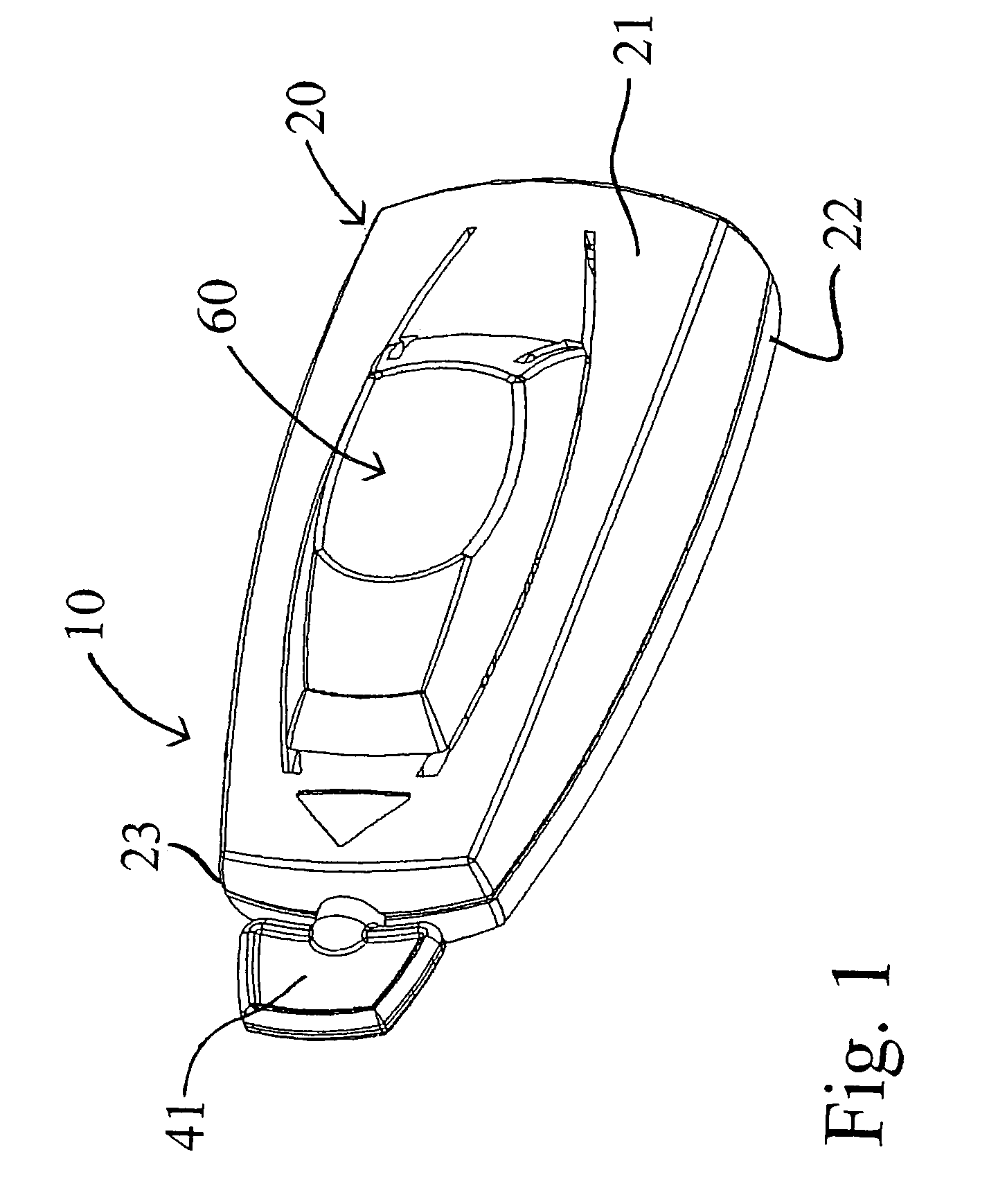
[0046]FIGS. 1-5 are perspective views of the preferred embodiment of the present invention. FIG. 1 illustrates the lancet device shown generally as 10 in its cocked position in which it is stored until ready for use. The body 20 of the device includes upper body portion 21 and lower body portion 22. Upper and lower body portions 21 and 22 may either be hingedly connected or may be separately formed and placed together in the position shown in FIG. 1 during the assembly process. A trigger shown generally as 60 in FIG. 1 is carried by upper body portion 21. Trigger 60 is shown in its first raised position in which the device is cocked. A plastic twist off safety cap 41 is shown extending outwardly from the distal end 23 of body 20. Cap 41 is integrally molded with the needle carrier assembly 40.

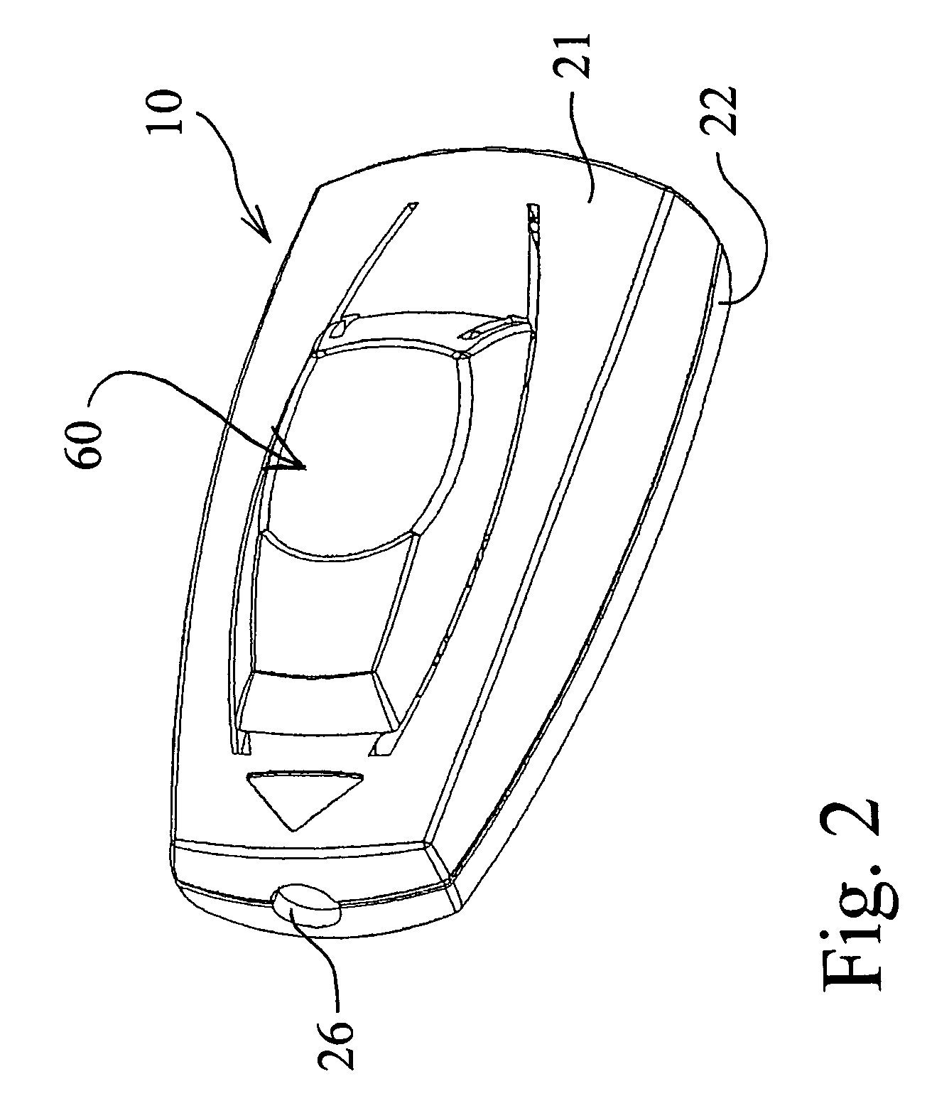
[0047]FIG. 2 illustrates the lancet device 10 after the safety cap 41 has been removed and the needle tip 45 (see FIG. 13) is exposed internally of the device and the device is ready to be fire...


PUM


Abstract

A single-use lancet device is provided for drawing capillary blood samples. The device includes a body having an upper portion and a lower portion and a trigger carried by the upper portion of the body. The trigger is movable between a first raised position wherein the device is cocked and a second depressed position wherein the device is fired. A needle assembly is provided which is movable between a cocked position and a striking position. A free-floating drive spring is provided for moving the needle assembly from its cocked position to its striking position. A bounceback spring is integrally molded with the needle assembly and includes a pair of generally V-shaped spring arms. A trigger bar has a first position wherein it holds the needle assembly in its cocked position, and the trigger bar has a second position wherein it allows the needle assembly to move to its striking position as the drive spring expands. The trigger carries a pair of guillotine-type blades which sever the trigger bar and thereby releases the needle assembly from its cocked position. Alternate trigger bars are provided which may be deformed rather than severed. The device is also capable of assembly by automatic equipment. The device is incapable of a second use because of the deformation or severing of the trigger bar.

Description

CROSS REFERENCE TO RELATED APPLICATIONS[0001]This application claims the benefit of and priority from U.S. provisional applications Ser. No. 60 / 422,630 filed Oct. 29, 2002 and Ser. No. 60 / 446,166 filed Feb. 7, 2003.BACKGROUND AND SUMMARY OF THE INVENTION[0002]The present invention relates generally to single-use lancets for drawing capillary blood samples. In particular, the present invention provides a single-use lancet which for safety reasons is not capable of being used more than once. Reuse is prevented by a unique trigger mechanism which in the preferred embodiment is irrevocably broken upon firing. The dire consequences of reuse, such as the spread of hepatitis or HIV, are thereby avoided. Furthermore, the present invention is designed so that it may be assembled by automatic machinery. Automatic assembly reduces the cost of the device and assures the highest quality finished product.[0003]Reliable attachment of the main spring to the rear end of the lancet and to the inner b...

Claims


Application Information

Patent Timeline
Patent Type & Authority Patents(United States)
IPC IPC(8): A61B17/3209A61B5/151A61B5/15A61B17/14A61B17/32A61M
CPCA61B5/1411A61B5/15142A61B5/151A61B5/150022A61B5/150412A61B5/150549A61B5/150618A61B5/150717A61B5/150824A61B5/150923A61B5/15113A61B5/15117A61B5/15144A61B5/150503
Inventor LEVIN, PAUL D.MOORE, ROBBY JAYLEVIN, DAVID M.ACKLEY, TEDHARDING, JOHN D.
Owner AMBI INC
Why Eureka
Try Eureka