Apparatus and method for connecting spinal vertebrae

a spinal vertebrae and appendix technology, applied in the field of appendix and a method for connecting spinal vertebrae, can solve the problems of inability to completely or significantly prevent scarring of dura and nerve roots, and continue to have back and leg pain. , to achieve the effect of stabilizing the spine, compact structure, and retaining spinal flexibility

Inactive Publication Date: 2007-10-16
LESFACETS LLC
View PDF1 Cites 198 Cited by
  • Summary
  • Abstract
  • Description
  • Claims
  • Application Information

AI Technical Summary

Benefits of technology

[0011]Among the advantages of this invention may be one or more of the following. The implantable spinal stabilization device stabilizes the spine, while allowing the patient to retain spinal flexibility by preserving motion between adjacent vertebras. This spinal stabilization device may be implanted percutaneously along the sides left and right of the spine utilizing minimally invasive surgery, i.e., without the

Problems solved by technology

However, when the vertebrae are misaligned or a constriction 45 is formed in the spinal canal, the nerves get compressed 44a and may cause back pain, leg pain or other neurological disorders.
Scarring is considered a major cause for failed back syndrome in which patients continue to have back and leg pain after spinal surgery.
However, no material as yet has been used that completely or significantly prevents scarring of the dura and nerve roots after spine surgery in humans.
Furthermore, laminectomy predisposes the patient to instability through the facet joints and may lead to post-laminectomy kyphosis (abnormal forward curvature of the spine), pain, and neurological dysfunction.
However, spinal fusion limits

Method used


Image

  • Apparatus and method for connecting spinal vertebrae
  • Apparatus and method for connecting spinal vertebrae
  • Apparatus and method for connecting spinal vertebrae

Examples


Embodiment Construction

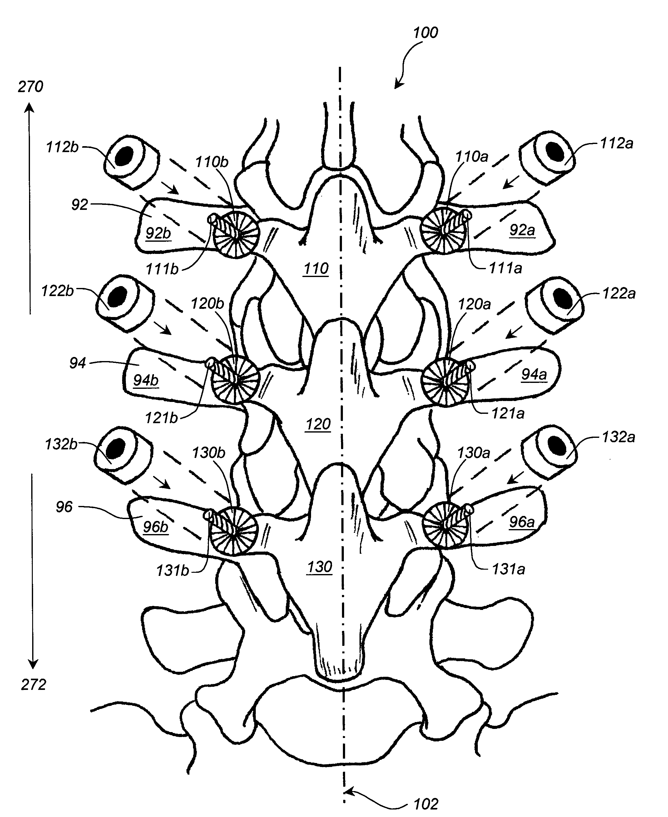
[0029]Referring to FIG. 2, an implantable spine stabilization device 100 connects vertebra 92 to adjacent vertebra 94 and vertebra 94 to adjacent vertebra 96. The spine stabilization device 100 includes modular components 110, 120, and 130. Modular components 110, 120, and 130 have circular ends 110a and 110b, 120a and 120b, 130a and 130b, respectively, that attach to pedicles 92A, 92B, 94A, 94B, 96A, and 96B of vertebra 92, 94 and 96, respectively, via pedicle screws 111a, 111b, 121a, 121b, 131a, and 131b, respectively. Modular components 110, 120, and 130 replace the resected laminas, pars interarticularis, facets and spinous processes of the vertebra 92, 94, and 96, respectively. Modular component 110 is articulately connected to component 120 along the midline 102 of the device 100 and the corresponding vertebrae 92 and 94, shown in FIG. 6. Similarly modular component 120 is articulately connected to component 130. Additional modular components may be added to extend the spine s...


PUM

PropertyMeasurementUnit
Lengthaaaaaaaaaa
Lengthaaaaaaaaaa
Lengthaaaaaaaaaa

Abstract

An orthopedic implantable device articulately connecting a first spinal vertebra to an adjacent second spinal vertebra includes a pair of first components adapted to be attached to locations left and right of a midline of the first vertebra, respectively; and a pair of second components adapted to be attached to locations left and right of a midline of the second vertebra, respectively. Each of the first components includes a body and a male articulation member attached to the first component body and each of the second components includes a body and a female articulation member attached to the second component body. The first components are articulately connected to the second components by engaging the male articulation members to the female articulation members, thereby articulately connecting the first vertebra to said second vertebra along lines left and right of the midlines, respectively.

Description

CROSS REFERENCE TO RELATED CO-PENDING APPLICATIONS[0001]This application is a continuation in part of U.S. application Ser. No. 10 / 364,847 filed on Feb. 11, 2003 now U.S. Pat. No. 6,669,729, and entitled APPARATUS AND METHOD FOR THE REPLACEMENT OF POSTERIOR VERTEBRAL ELEMENTS the contents of which are expressly incorporated herein by reference.FIELD OF THE INVENTION[0002]The present invention relates to an apparatus and a method for connecting spinal vertebrae, and more particularly to an apparatus and a method that connects spinal vertebrae while preserving spinal stability and mobility.BACKGROUND OF THE INVENTION[0003]The human spine 29 comprises individual vertebrae 30 that interlock with each other to form a spinal column, shown in FIG. 1A. Referring to FIGS. 1B, 1C, and 1D, each vertebra 30 has a cylindrical bony body (vertebral body) 32, two pedicles 48 extending from the vertebral body 32, a lamina 47 extending from the pedicles 48, three winglike projections (two transverse ...

Claims


Application Information

Patent Timeline
IPC IPC(8): A61F2/44A61B17/00A61B17/70A61B19/00A61F2/00A61F2/02A61F2/28
CPCA61B17/7025A61F2/4405A61B17/00234A61F2310/00359A61B17/7062A61B17/7064A61B19/54A61B2017/00004A61F2/28A61F2002/30062A61F2210/0004A61F2310/00017A61F2310/00023A61F2310/00071A61F2310/00179A61B17/7007A61B90/39A61B17/7059A61B17/7071
Inventor CHIN, KINGSLEY RICHARD
Owner LESFACETS LLC
Why Eureka
Try Eureka