
Computerized electricity system having an arc fault detecting sub-system

a computerized electricity system and sub-system technology, applied in the direction of position/direction control, instruments, emergency protective arrangements for limiting excess voltage/current, etc., can solve the problems of arc fault, excessive heating temperature, damage to the insulation of the wiring,

Inactive Publication Date: 2007-10-16
TARGET HI TECH ELECTRONICS
View PDF4 Cites 64 Cited by
  • Summary
  • Abstract
  • Description
  • Claims
  • Application Information

AI Technical Summary

Benefits of technology

[0023]According to still further features in the described preferred embodiments, the processing unit is co...

Problems solved by technology

Corroded, worn or aged wiring or insulation, worn power cords, old wall outlets with insufficient contact pressure, electrical stress from repeated overloading, etc., may result in an arc fault.
These conditions may damage the insulation of the wiring and create excessive heating temperatures.
Arc faults may result in a fire depending on various conditions, such as if combustible materials are in close proximity.
There are also various conditions that may result in a false arc fault.
For example, the occurrence of an arc fault in one branch circuit of a power distribution system may generate a false arc in another branch circuit.
As a result, circuit breakers in more than one branch circuit may erroneously trip.
Another example is a relatively noisy load such as an electric drill creating a high frequency disturbance in the circuit, which may appear to be an arc fault.
The other type of arc fault, the momentary contact of electrical conductors, may be considered more problematic.
Since the current in the arc may be limited to less than the trip rating of an associated circuit breaker, such arcs may become persistent without observation and may result in certain conditions.
Contact arcs may be caused by springs in switches that become worn which, in turn, may reduce the forces that hold electrical contacts together.
For example, aluminum wiring that contacts copper wiring may oxidize at the contact points.
In this case, a non-conductive layer may build up over time between the contact points and arcing may result.
As the plug is heated by resistance heating, insulating materials around the contacts may eventually melt and flow into the contact area, preventing proper contact from being made.
It is believed that various circuit breakers are not specifically designed to guard against sputtering arcs.
All of these arc fault detection systems are plagued by false alarms, i.e., the systems identify an arc fault and trigger a current shut-off, in situations in which there is no genuine arc fault, or the arc fault is benign.
Low quality and / or aging of a switch may also cause transient arc-fault type effects in the circuit.
It must be emphasized that the efficacy of an arc fault detection system that triggers, in response to a benign arc fault event—a current shut-off, is greatly compromised, and in many applications, the disadvantages of implementing such a system easily outweigh the potential benefit.

Method used


Image

  • Computerized electricity system having an arc fault detecting sub-system
  • Computerized electricity system having an arc fault detecting sub-system
  • Computerized electricity system having an arc fault detecting sub-system

Examples


Embodiment Construction

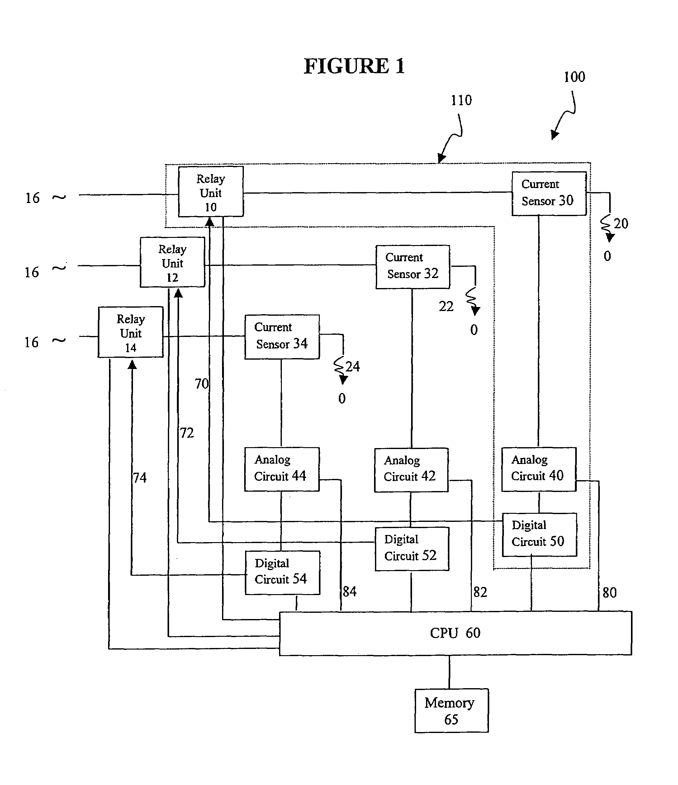
[0039]The present invention is a computerized electricity system having an arc fault detecting sub-system and method for operating such a sub-system.

[0040]The principles and operation of the arc fault detecting system and method according to the present invention may be better understood with reference to the drawings and the accompanying description.

[0041]Before explaining at least one embodiment of the invention in detail, it is to be understood that the invention is not limited in its application to the details of construction and the arrangement of the components set forth in the following description or illustrated in the drawing. The invention is capable of other embodiments or of being practiced or carried out in various ways. Also, it is to be understood that the phraseology and terminology employed herein is for the purpose of description and should not be regarded as limiting.

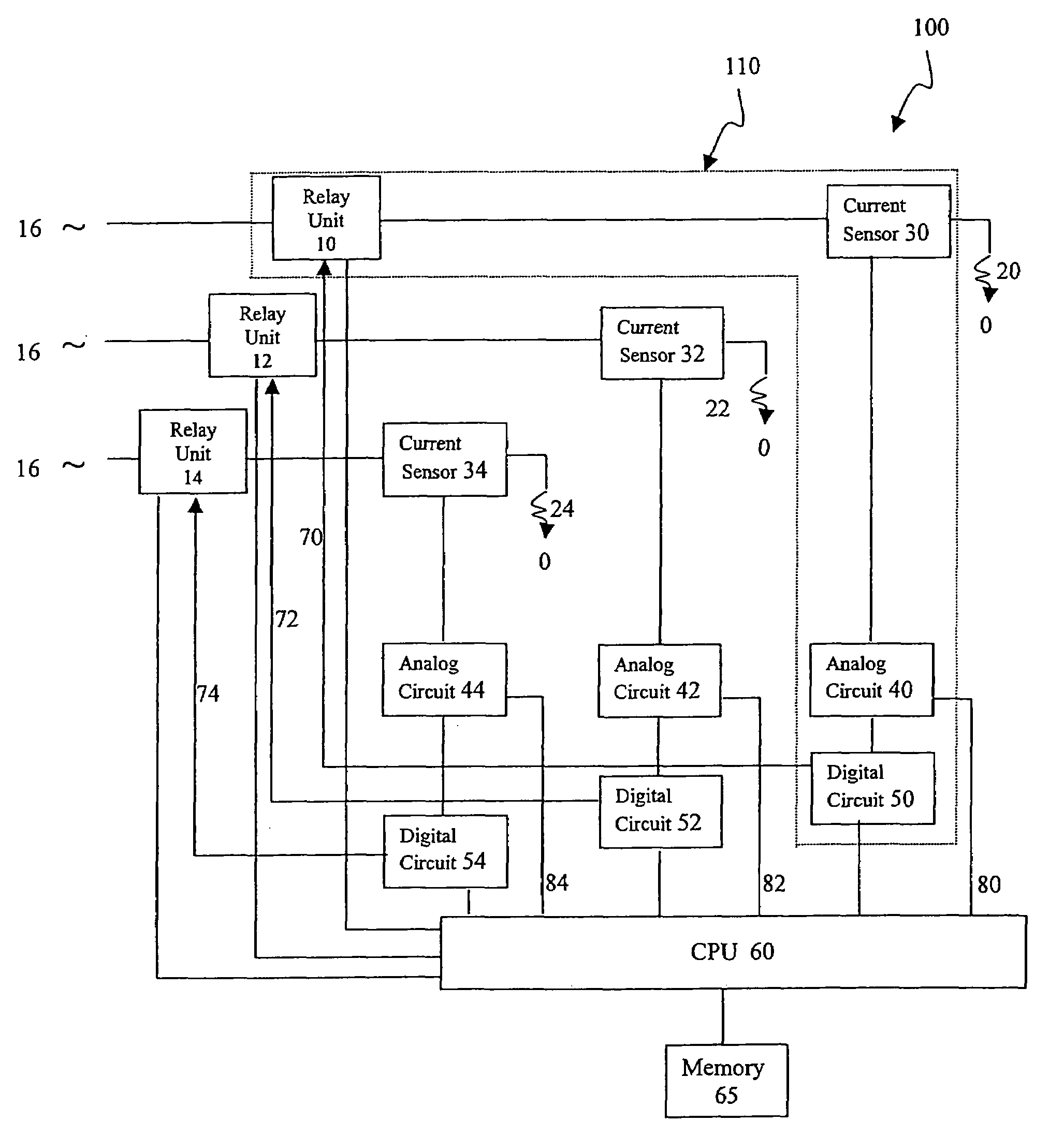
[0042]Referring now to the drawings, FIG. 1 is a block diagram of a preferred embodiment of fault ...


PUM


Abstract

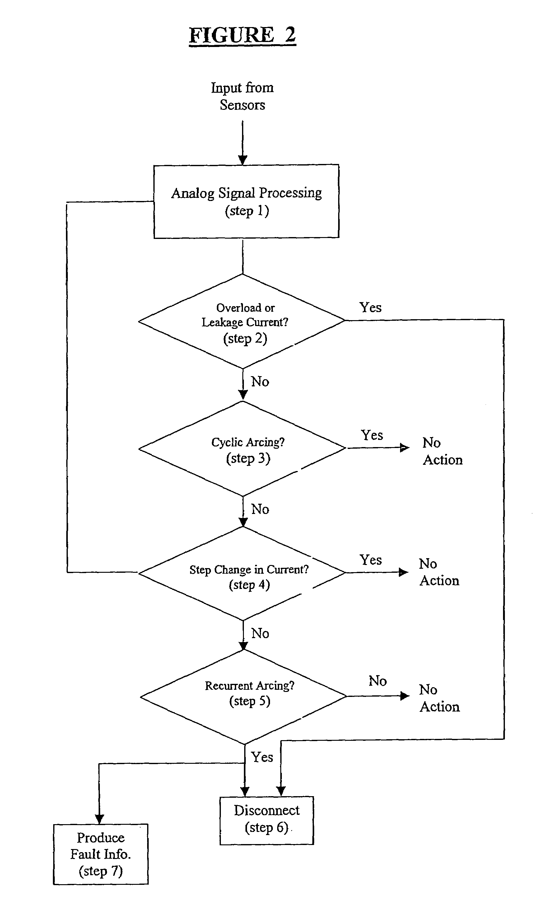
A computerized electricity system for connecting loads to a power source, including: (a) an arc fault detecting sub-system having at least one module including: (i) a relay unit, electrically associated with a particular load, for connecting and disconnecting to a power source; (ii) a current source for measuring a current being delivered from the power source to the load, to produce a current measurement; (iii) an analog circuit for receiving the current measurement from the current sensor, and for producing an analog signal based on the current measurement, and a second signal for indicating a potential arc fault event, and (iv) a digital circuit for receiving the second signal from the analog circuit and producing data, and (b) a processing unit connected to each module, so as to receive data corresponding to the analog signal, and the data from the digital circuit, the processing unit for identifying the arc faults, and wherein the processing unit is configured to command the relay unit to disconnect the current in response to identifying the arc faults, and wherein the processing unit is configured to provide this command only if several pre-determined conditions are met, (I) after detection of the potential arc fault event, the current measurement remains substantially unchanged, and (II) after a detection of at least one addition potential arc fault event, the arc fault events are found to be acyclic.

Description

FIELD AND BACKGROUND OF THE INVENTION[0001]The present invention relates to computerized electricity systems, more particularly, to fault detecting systems and methods, and, more particularly, to an arc fault detecting system and method.[0002]There are various conditions that may cause an arc fault. Corroded, worn or aged wiring or insulation, worn power cords, old wall outlets with insufficient contact pressure, electrical stress from repeated overloading, etc., may result in an arc fault. These conditions may damage the insulation of the wiring and create excessive heating temperatures. Arc faults may result in a fire depending on various conditions, such as if combustible materials are in close proximity.[0003]There are also various conditions that may result in a false arc fault. For example, the occurrence of an arc fault in one branch circuit of a power distribution system may generate a false arc in another branch circuit. As a result, circuit breakers in more than one branch...

Claims


Application Information

Patent Timeline
IPC IPC(8): G01R31/08H01H9/50H02H3/00
CPCH02H1/0015H02H1/0092
Inventor WITTNER, LUPU
Owner TARGET HI TECH ELECTRONICS
Learn More