
Apparatus and Method for the Production of Particles

Inactive Publication Date: 2013-04-18
XSPRAY MICROPARTICLES AB
View PDF5 Cites 7 Cited by
  • Summary
  • Abstract
  • Description
  • Claims
  • Application Information

AI Technical Summary

Benefits of technology

The present invention relates to improving the manufacturing process of apparatuses that increase productivity. The inventors found that using dispensers that produce pulsed flow can help avoid issues with flow between dispensers and ensure consistent particle formation. This also enables better temperature control during particle formation. Additionally, the inventors discovered that dividing the main flow line into sublines with one or more dispensers can simplify the control of particle size and morphology. An injector is used to induce pulses and an excess function is used to handle the increase in pressure caused by the injector. Overall, this invention helps reduce manufacturing costs and improve the efficiency of the production process.

Problems solved by technology

This composition of the fluid mixture at the place where particles formed affects the particles characteristics and thus a static variant is not appropriate for production of consequent batch of powder.
The problems encountered in the field are to a large extent related to the particle formation arrangements used.
There is also a risk for variations in particle characteristics over time due to unstable (uncontrolled) flow through the outlet of the dispenser, e.g. due to clogging when depressurizing / expanding fluid solutions through a nozzle into a particle formation chamber.
The expanding of the fluid solution through a nozzle will lower the temperature of the dispenser which also will create flow problems, the severity of which will depend on the pressure drop during expansion.
Separate pumps will be expensive and in the long run likely not to be competitive.
To split a flow in equal parts by branchings can be challenging especially when there is a risk for uncontrolled variations in pressure fall, e.g. by clogging of single dispensers.

Method used


Image

  • Apparatus and Method for the Production of Particles
  • Apparatus and Method for the Production of Particles
  • Apparatus and Method for the Production of Particles

Examples


example 2

Pure Drug Substance Particle Formation by SAS (Solvent Anti-Solvent)

[0204]1. Inject a pulsed flow of a solution of 0.8% nicotinic acid in ethanol at 1 ml / min by the use of an actuated injector into a flow of 100 g / min supercritical CO2 at 90 bar and 90° C. passing through a flow-through particle formation chamber in order to obtain sub- to micrometer particles in the chamber.[0205]2. Allow carbon dioxide and ethanol to continuously leave the chamber during the formation of the particles.

example 3

Particle Formation and Coating by Synchronized SAS (Solvent Anti-Solvent)

[0206]1. Use a first actuated injector to deliver a pulsed flow of a solution of 0.8% nicotinic acid in ethanol at 1 ml / min into a flow of 100 g / min supercritical CO2 at 90 bar and 90° C. which passes through a particle formation chamber in order to obtain sub- to micrometer particles.[0207]2. Use a second actuated injector to deliver a pulsed flow of a solution of 0.1% of PVP K30 in acetone at a flow of 0.1 ml / min to the flow of supercritical CO2 at a position downstream of the first injector in order to coat the particles formed by injection of the solution. The pulses of the two injectors are synchronized with each other (flow pulses are in synchrony or asynchrony).[0208]3. Allow carbon dioxide and the ethanol and acetone delivered to the chamber in steps (1) and (2) to continuously leave the chamber during the formation of the particles.

example 4

Solid Dispersion Formation by Spray Drying

[0209]1. Deliver a pulsed flow of 5% (w / v) solution of piroxicam / PVP K25 (weight ratio=1:4) in a mixture of ethanol / acetone (volume ratio=1:4) at a flow of 1-5 ml / min by an actuated injector into a flow of a drying gas set to 10-50 m3 / hour which passes through a particle formation chamber at 60-110° C.[0210]2. Allow the gas / ethanol / acetone mixture to continuously leave the chamber.

[0211]For spray drying methods using standard equipment refererence is made to “Formation and Characterization of Solid dispersions of Piroxicam and Polyvinylpyrrolidone Using Spray drying and Precipiatation with Compressed Antisolvent”, K. Wu et al., Journal of pharmaceutical Sciences, Vol. 98, No. 7, July 2009.


PUM

PropertyMeasurementUnit
Pressureaaaaaaaaaa
Flow rateaaaaaaaaaa
Distanceaaaaaaaaaa

Abstract

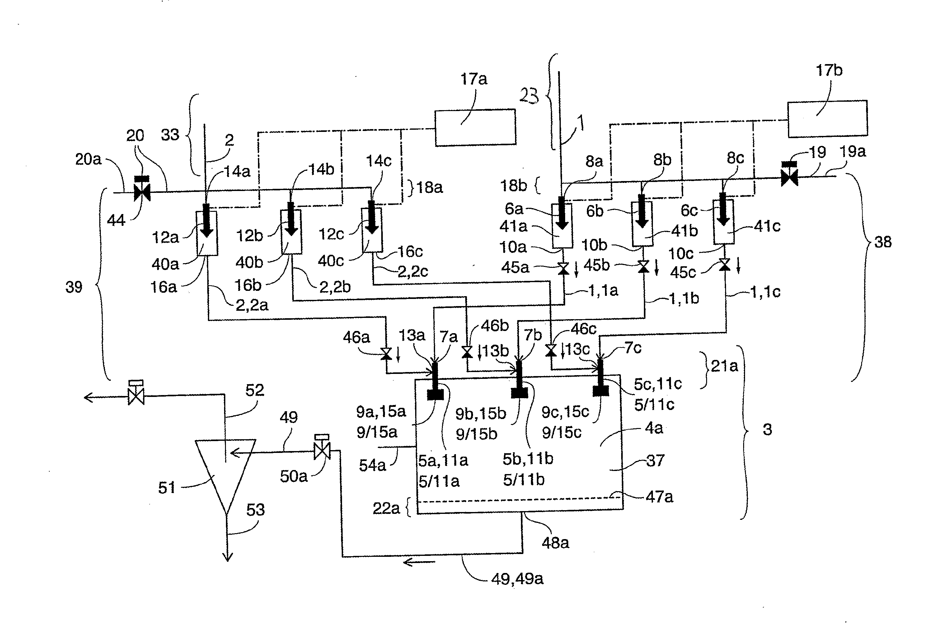
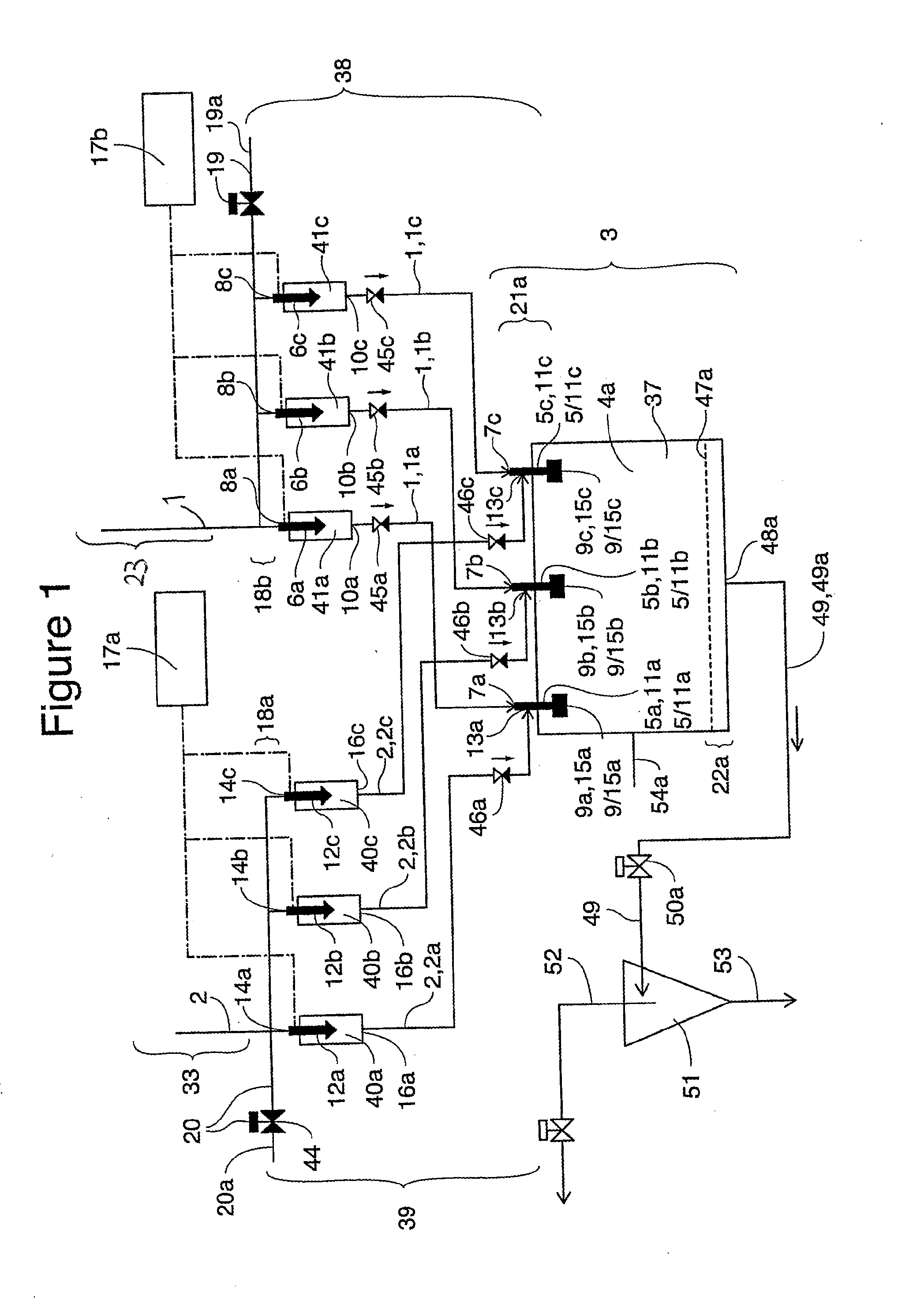
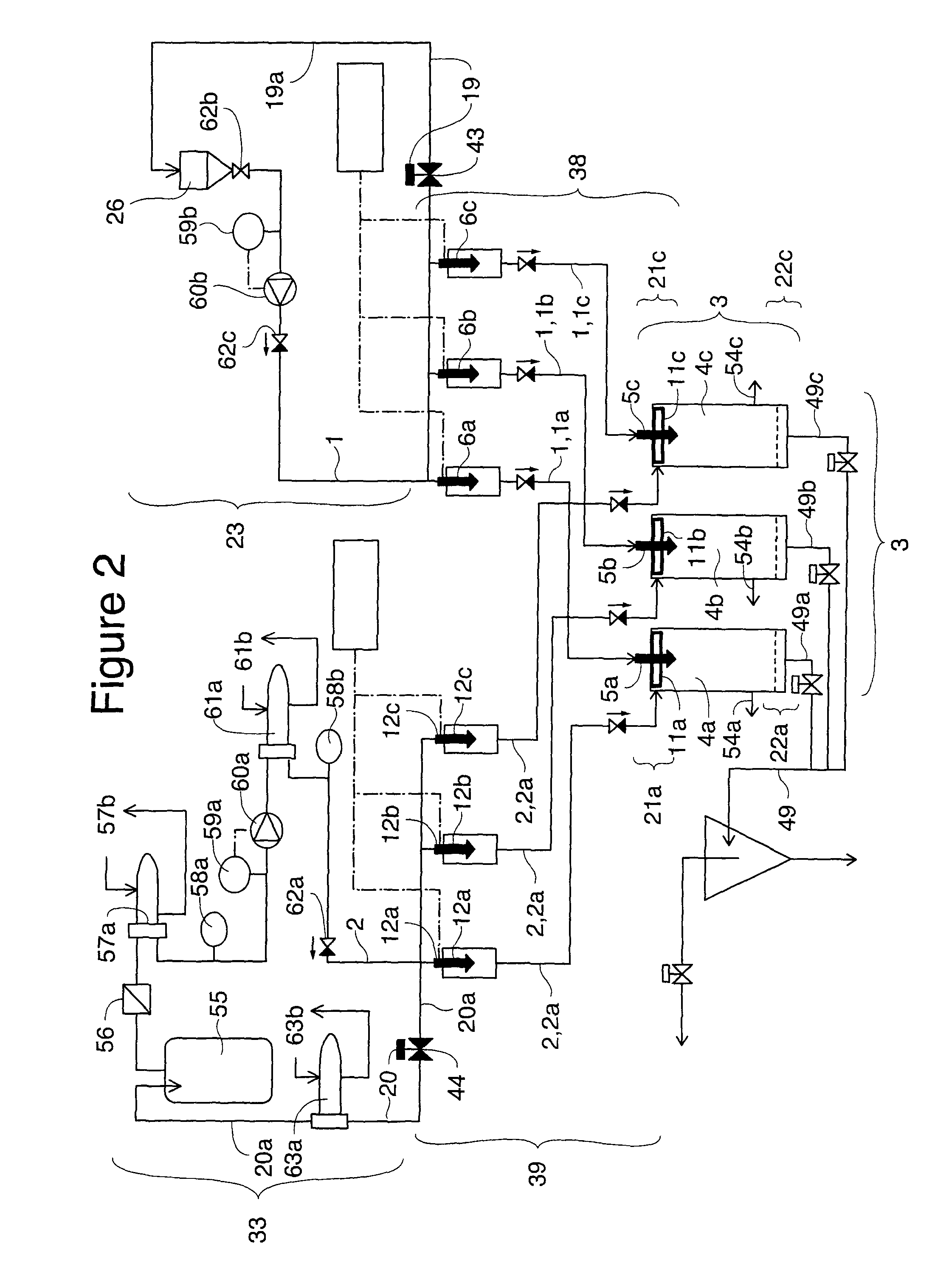
An apparatus for the production of particles of a substance by dynamic precipitation of the substance from a fluid solution containing the substance dissolved in a fluid solvent. The apparatus is characterized by comprising A) a first main flow line FL1 (1) intended for a first pressurized fluid F1 and encompassing in its downstream part (dFL1) (38) one, or more dFL1 sub-lines (1a,b,c), where a) every dFL1 subline • comprises one or two serially linked flow-through dispensers for F1 (5a,b,c. and 6a, b, c) and • is functionally equal to the other dFL1 sublines, and b) each of the dispensers • has an inlet (7a,b,c. and 8a,b,c, respectively) and an outlet (9a,b,c. and 1 Oa,b,c . . . , respectively) for flow, and • is functionally equal with the corresponding dispensers in the other dFL1 sublines, and B) a particle formation arrangement (4) comprising a) one or more flow-through particle formation chambers (3a,b,c . . . ), and b) the downstream dispensers (5a,b,c.) of said one or two dispensers (5a,b,c . . . ,6a,b,c.) with one, two or more dispensers per chamber, at least one of the one or two dispensers (5a,b,c . . . ,6a,b,c.) is an injector which is capable of being repeatedly activated enabling a pulsed flow through the outlet of the injector.

Description

FIELD OF THE INVENTION[0001]This invention relates to an apparatus and / or a method for the dynamic production of particles which contain a substance.[0002]Particles produced according to the invention may be used in a large number of applications, e.g. in pharmaceutical compositions.BACKGROUND TECHNOLOGY[0003]The inventive method belongs to generic methods which comprise the step of removing solvent from a pressurized fluid solution containing the substance in a dissolved or suspended or dispersed form by depressurizing or expanding the solution in a particle formation arrangement. The fluid solution may be mixed with one or more other fluids before or during the particle formation step. The particles obtained may be a) porous and / or non-porous, and / or b) hard or elastic including soft, and c) may or may not contain other substances. Particle formation typically comprises precipitation of a substance which is to be incorporated into the particles.[0004]There are two main variants of...

Claims


Application Information

Patent Timeline
IPC IPC(8): B29C67/00
CPCA61K9/14B29C67/00B01J2/06A61K9/1635B01J2/02B01J2/18
Inventor DEMIBUKER, MUSTAFAJESSON, GERALD
Owner XSPRAY MICROPARTICLES AB
Learn More