Hierarchical virtual private LAN service protection scheme

a virtual private lan and protection scheme technology, applied in the field of communication networks, can solve the problems of long period of traffic outage, inability to initiate failure protection, and inherently slow

Active Publication Date: 2007-10-16
CORRECT TRANSMISSION LLC
View PDF35 Cites 79 Cited by
  • Summary
  • Abstract
  • Description
  • Claims
  • Application Information

AI Technical Summary

Benefits of technology

[0019]In preferred embodiments of the present invention, a VPN comprises primary core nodes, as in a conventional hierarchical VPLS network, along with one or more standby core nodes. Each standby core node has the same topological image in the network (i.e., the same connections) as a corresponding primary core node which it protects. Therefore, if the primary core node fails, the remaining nodes in the network simply redirect all connections from the failed primary core node to the corresponding standby core node. Since the standby core node has the same topology as the failed primary core node, the remaining nodes in the network do not need to re-learn MAC table addresses, and are thus able to recover quickly from the failure. In addition, since there is no topology change, there is no need to clear the MAC tables, so that packet flooding is reduced significantly.
[0020]Furthermore, a network designed in accordance with the present invention can handle multiple simultaneous node failures, as long as at least one core node from each pair of primary and standby core nodes does not fail.

Problems solved by technology

VPLS networks are still in the development stage, and there are as yet no clear standards for loop prevention in such networks.
The failure protection scheme suggested by Lasserre et al., however, can result in a long period of traffic outage if a virtual connection fails between an edge node and a core node, or if a core node fails.
In most cases, initiation of failure protection depends on MAC address aging and learning schemes, which are inherently slow.
In addition, the need to handle both standard connections (to edge nodes and other core nodes) and backup protection connections (to edge nodes) complicates the design of the VPLS core nodes and of the network as a whole.

Method used


Image

  • Hierarchical virtual private LAN service protection scheme
  • Hierarchical virtual private LAN service protection scheme
  • Hierarchical virtual private LAN service protection scheme

Examples


Embodiment Construction

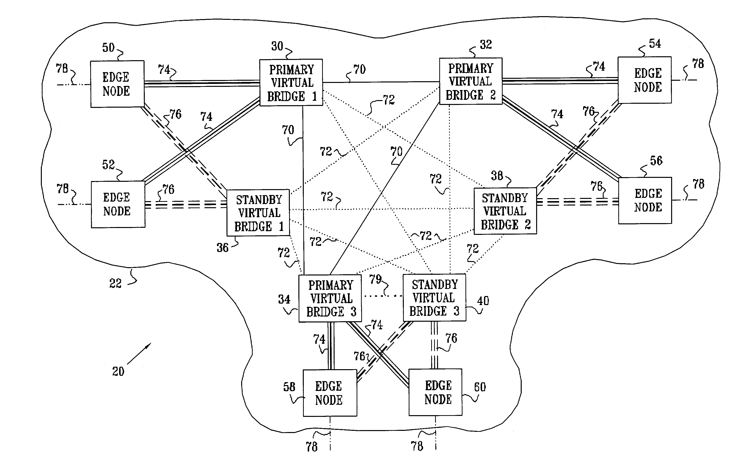
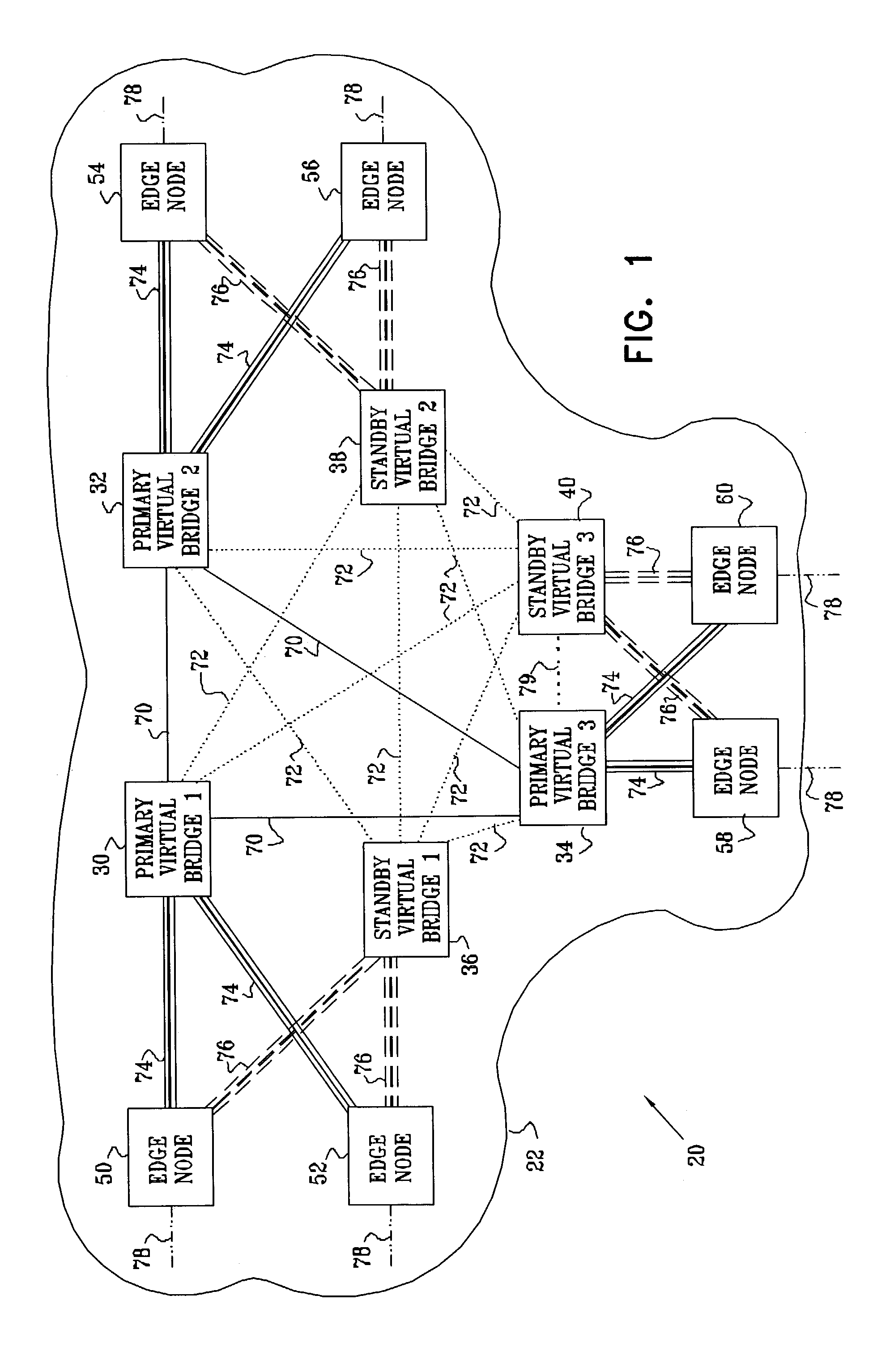
[0042]FIG. 1 is a block diagram that schematically illustrates a VPN 20 with a hierarchical VPLS topology, implementing a protection scheme in accordance with a preferred embodiment of the present invention. VPN 20 is built around a virtual private LAN service (VPLS), operating within a network 22, typically an IP or MPLS network. The VPLS is based on virtual bridges 30, 32, 34, 36, 38, and 40, or VPLS-capable PEs, which are connected by PWs 70, 72, 74 and 76 through network 22. Although for clarity of illustration, network 22 includes only a small number of PEs and represents only a single VPLS instance, the principles embodied in this network may be extended in a straightforward manner to larger networks and to multiple VPLS instances.

[0043]Three primary virtual bridges 30, 32 and 34, referred to as primary core nodes, are connected with each other in a full mesh with PW connections 70. Typically, the PW connections comprise MPLS tunnels, but they may alternatively comprise virtua...


PUM


Abstract

A data communication network includes a plurality of primary virtual bridges, interconnected by primary virtual connections so as to transmit and receive data packets over the network to and from edge devices connected thereto. One or more backup virtual bridges, each associated with at least one of the primary virtual bridges, are connected by at least one secondary virtual connection to at least another one of the primary virtual bridges, so that upon a failure of one of the primary virtual bridges with which it is associated, the backup virtual bridge transmits and receives the data packets over the network via the at least one secondary virtual connection in place of the at least one of the primary virtual bridges.

Description

FIELD OF THE INVENTION[0001]The present invention relates generally to communication networks, and specifically to methods and systems for providing virtual private LAN services (VPLS).BACKGROUND OF THE INVENTION[0002]Local Area Networks (LANs) connect computing systems together. LANs of all types can be connected together using Media Access Control (MAC) bridges, as set forth in the “IEEE Standard for Information Technology, Telecommunications and Information Exchange between Systems, Local and Metropolitan Area Networks, Common Specifications, Part 3: Media Access Control (MAC) Bridges,” published as ANSI / IEEE Standard 802.1D (1998), which is incorporated herein by reference. The 802.1D standard is available at standards.ieee.org / getieee802 / download / 802.1D-1998.pdf.[0003]Each computing system connects to a LAN through a MAC device. MAC bridges that implement the 802.1D standard allow MAC devices attached to physically separated LANs to appear to each other as if they were attached...

Claims


Application Information

Patent Timeline
Patent Type & Authority Patents(United States)
IPC IPC(8): G06F11/00H04L12/46H04L69/40
CPCH04L12/4641H04L69/40H04L2212/0025H04L2212/00
Inventor ZELIG, DAVIDBRUCKMAN, LEONKOTSER, YOAV
Owner CORRECT TRANSMISSION LLC
Why Eureka
Try Eureka