
Method and apparatus for functionally verifying a physical device under test

a physical device and functional verification technology, applied in the direction of error detection/correction, cad circuit design, instruments, etc., can solve the problems of increasing the likelihood of design errors, increasing the difficulty of design verification, and increasing the difficulty of time-consuming

Active Publication Date: 2007-10-16
VERISITY
View PDF13 Cites 28 Cited by
  • Summary
  • Abstract
  • Description
  • Claims
  • Application Information

AI Technical Summary

Benefits of technology

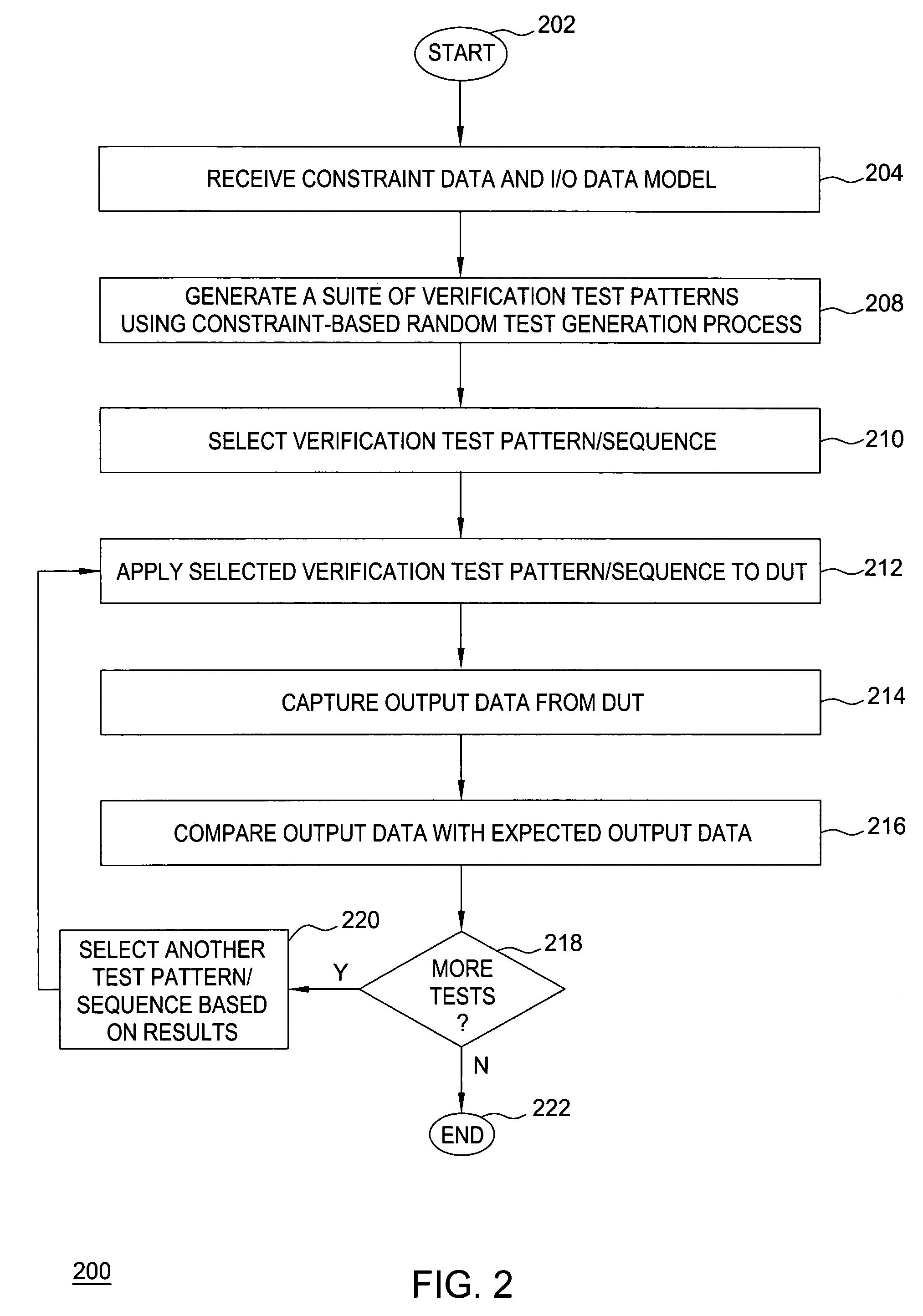
"The patent describes a method for testing a physical device to make sure it works properly. This is done by creating data that describes the testing process and then applying it to the device. The data is generated based on a set of rules and information about the device. The testing process involves applying the data to the device and collecting the output data. This output data is then compared with the expected output data to verify the device's design. Overall, this method helps ensure the device is functionally sound."

Problems solved by technology

As designs become more complex, the likelihood of design errors increases and design verification becomes increasingly difficult and time consuming.
Verifying an actual device is more complex than verifying a simulation model of the device.
Thus, the application of test vectors and analysis of the results becomes nontrivial.
In addition, it is difficult and impractical to monitor the internal nodes of a design in the actual device, whereas such internal nodes are accessible in a simulation model.

Method used


Image

  • Method and apparatus for functionally verifying a physical device under test
  • Method and apparatus for functionally verifying a physical device under test
  • Method and apparatus for functionally verifying a physical device under test

Examples


Embodiment Construction

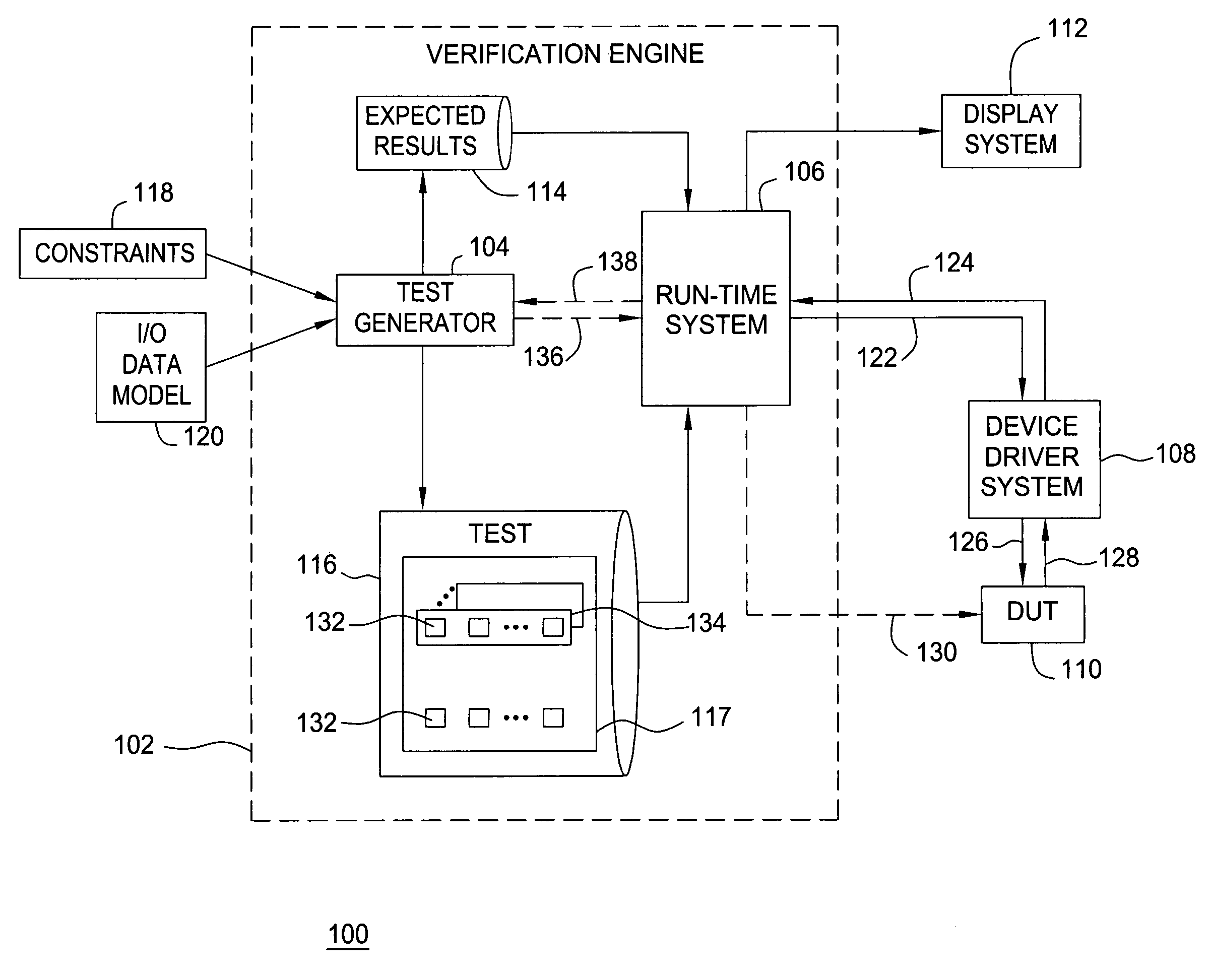
[0015]FIG. 1 is a block diagram depicting an exemplary embodiment of a system 100 for functionally verifying a physical device under test (DUT) in accordance with the invention. The system 100 includes a verification engine 102, a device driver system 108, a display system 112, and a DUT 110. The verification engine 102 generates data to verify that the DUT 110 functions in accordance with its specification (referred to herein as “verification test data”). The verification engine 102 tests the DUT 110 by interfacing with the device driver system 108 to apply the verification test data to the DUT 110. The DUT 110 processes the verification test data and produces verification test output data, which is provided to the verification engine 102 via the device driver system 108. The verification engine 102 compares the verification test output data to expected output data and reports the results to the display system 112 for display to a user, such as a verification engineer.

[0016]In part...


PUM


Abstract

Method, apparatus, and computer readable medium for functionally verifying a physical device under test (DUT) is described. In one example, verification test data is generated for the physical DUT using a constraint-based random test generation process. For example, the architecture, structure, and / or content of the verification test data may be defined in response to constraint data and an input / output data model. A first portion of the verification test data is applied to the physical DUT. Output data is captured from the physical DUT in response to application of the first portion of the verification test data. A second portion of the verification test data is selected in response to the output data. Expected output data for the physical DUT associated with the verification test data may be generated and compared with the output data captured from the DUT to functionally verify the design of the DUT.

Description

BACKGROUND OF THE INVENTION[0001]1. Field of the Invention[0002]The present invention generally relates to verifying circuit designs and, more particularly, to functionally verifying a physical device under test.[0003]2. Description of the Related Art[0004]The field of electronic design automation (EDA) is well established. A number of software tools are used to describe a circuit at various levels of granularity or specificity. Such tools include gate level descriptions, which specify the circuit in very great detail, to high level descriptions written in hardware description languages (HDLs), such as VERILOG or VHDL. Design verification is the process of determining whether an integrated circuit, board, or system-level architecture, exactly implements the requirements defined by the specification of the architecture for that device. As designs become more complex, the likelihood of design errors increases and design verification becomes increasingly difficult and time consuming.[0...

Claims


Application Information

Patent Timeline
Patent Type & Authority Patents(United States)
IPC IPC(8): G01R31/28
CPCG01R31/31704G06F17/5022G06F11/263G06F30/33
Inventor HOLLANDER, YOAV Z.KASHAI, YARON E.
Owner VERISITY
Learn More