Exhaust gas recirculation apparatus

a technology of exhaust gas recirculation and recirculation device, which is applied in mechanical equipment, lighting and heating equipment, machines/engines, etc., can solve the problems of inability to achieve the effect of cooling the high-temperature exhaust gas and circulating the cooled gas to the engine-intake side, and the egr valve and the switching valve are susceptible to heat, so as to improve the reliability and durability of the exhaust gas recirculation device. , the effect of improving

Active Publication Date: 2007-10-23
MITSUBISHI ELECTRIC CORP
View PDF17 Cites 45 Cited by
  • Summary
  • Abstract
  • Description
  • Claims
  • Application Information

AI Technical Summary

Benefits of technology

[0008]In such a way, it is arranged that in the exhaust gas recirculation passage where the EGR cooler is provided, the upstream and downstream sides of said EGR cooler are connected or associated by the bypass passage; by the valve controlling means used for controlling in switching operation the bypass valve for opening and closing this bypass passage, the timing period of flowing the high-temperature exhaust gas diverted from said EGR cooler into said EGR valve is set; and during the timing period, said high-temperature exhaust gas is diverted from said EGR cooler and flown into said EGR valve through said bypass passage. For this reason, there is an effect that it is possible to remove the deposits adhered to the exhaust gas recirculation passage, the EGR valve, and the bypass valve can be removed with the high-temperature exhaust gas to burn and dry the deposits only during said timing period, to thereby achieve an improvement of the pressure loss caused by the deposits and improve reliability and durability of the exhaust gas recirculation device. Moreover, because only during said timing period the high-temperature exhaust gas is circulated to the downstream side of the EGR cooler, there is an effect that said timing period can be set within the range where the EGR valve and bypass valve are thermally unaffected.

Problems solved by technology

In a conventional exhaust gas recirculation device, the device having a structure in which an exhaust gas recirculation passage (hereinafter, referred to as EGR pipe) is connected to an intake-and-exhaust passage of an engine and the EGR pipe is equipped with an EGR valve alone has the disadvantage that deposits such as suspended matters contained in the circulating exhaust gas deposit on the inner peripheral surface of the EGR pipe and the valve-rod sliding area of the EGR valve and further, there arise pressure losses and malfunctions of the EGR valve, caused by the deposit deposition thereon.
Because of this, an effect other than the deposit removal performed by the high-temperature exhaust gas, that is, the effect of cooling the high-temperature exhaust gas and circulating the cooled gas to the engine-intake side cannot be achieved.
Furthermore, there is a problem that the EGR valve and the switching valve are susceptible to heat due to the high-temperature exhaust gas.
Consequently, there is a problem that the high-temperature exhaust gas containing steam, unburned gas and oil passes through the EGR cooler, and thereby, condensed deposits adhere to the EGR valve, thus causing the EGR valve to stick.
As a result, there arises a serious problem that the incorporation is impractical.

Method used


Image

  • Exhaust gas recirculation apparatus
  • Exhaust gas recirculation apparatus
  • Exhaust gas recirculation apparatus

Examples


embodiment 1

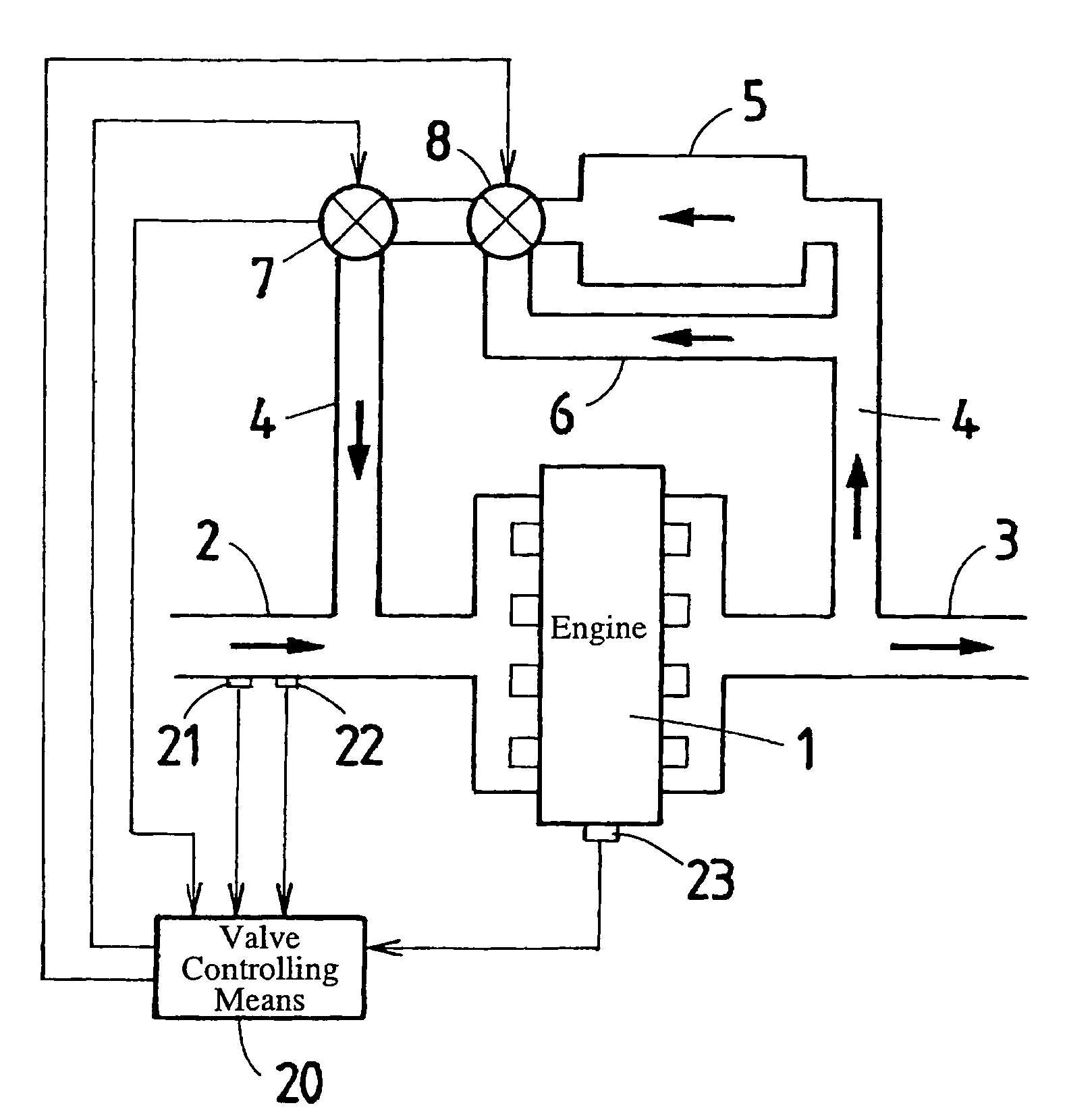
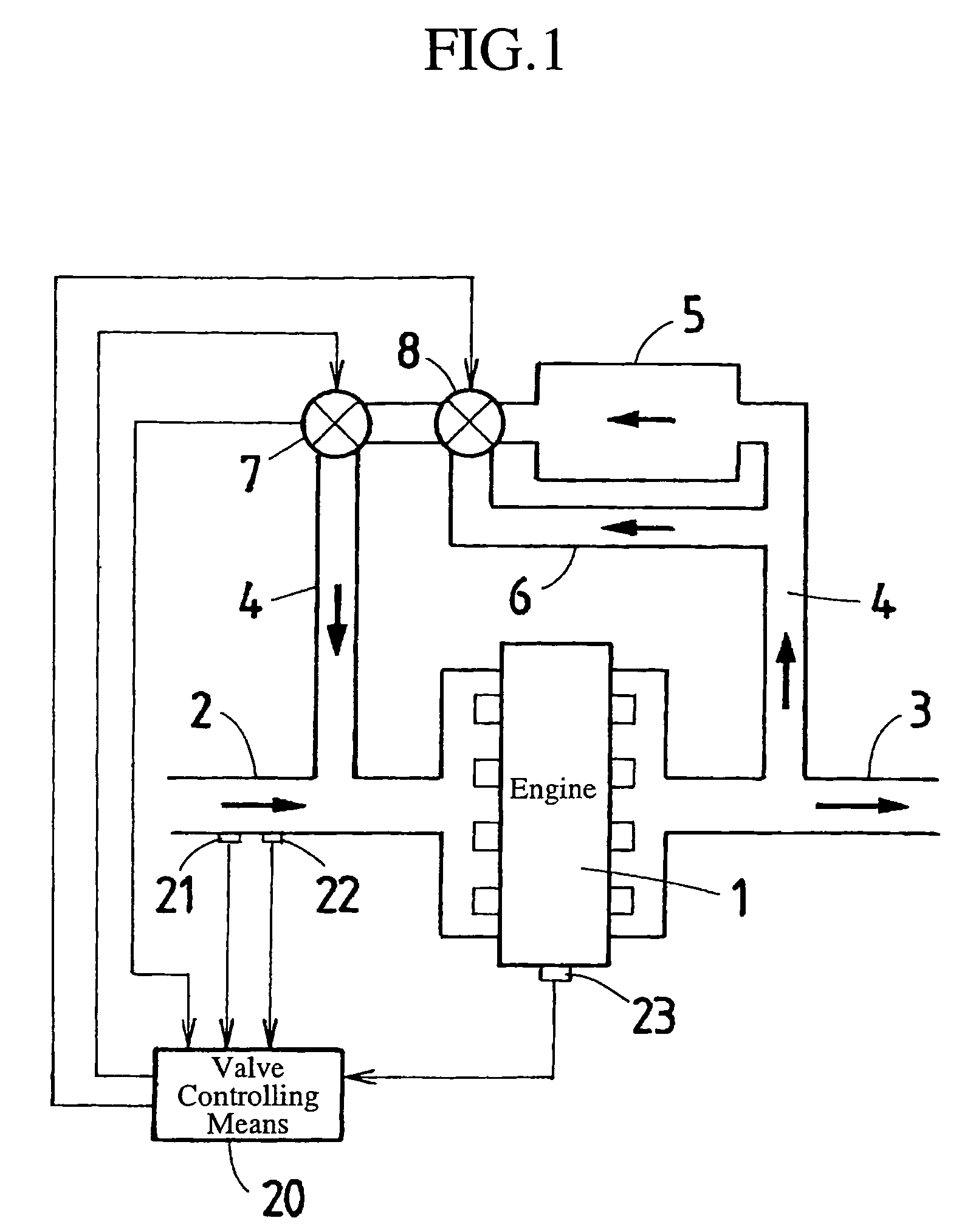
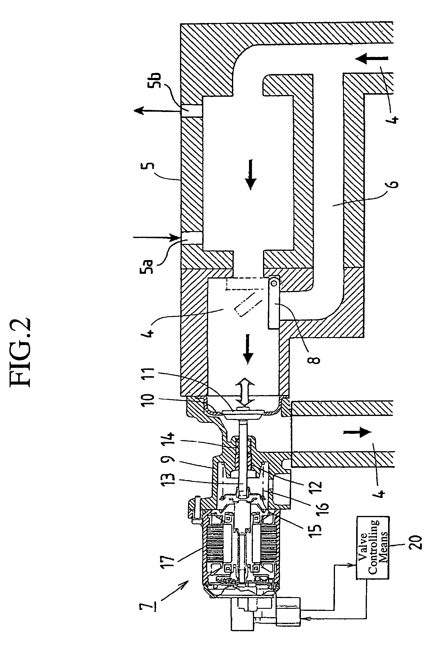
[0012]FIG. 1 is a schematic diagram for explaining the fundamental structure of an exhaust gas recirculation device in accordance with Embodiment 1 of the present invention, and FIG. 2 is an enlarged sectional view of the EGR valve shown in FIG. 1.

[0013]The exhaust gas recirculation device according to the present invention includes, as shown in FIG. 1, an exhaust gas recirculation passage (hereinafter referred to as EGR pipe) 4 that connects or associates the intake passage 2 and the exhaust passage 3 of an engine 1, and this EGR pipe 4 is provided with an EGR cooler 5. This EGR cooler 5 has a structure in which, for example, one end of each of many pipes (not shown) juxtaposed in spaced relationship collects in a single pipe, the single pipe is connected with a cooling water inlet port 5a, the other end of each of the pipes collects in another single pipe, and the single pipe is connected with a cooling water outlet port 5b. The exhaust gas is flown through the spaces between the ...

embodiment 2

[0023]In Embodiment 1, it is arranged that upon removing of the deposit, the bypass valve 8 is controlled to be switched to the valve position in which the outlet port of the EGR cooler 5 for the cooled exhaust gas is completely closed and the bypass passage 6 is completely opened with the output control signal from the valve controlling means 20. However, it can be also arranged that, when determining the timing of circulating the high-temperature exhaust gas based on the signals inputted from the various sensors, the valve controlling means 20 control and open the bypass valve 8 in an opening degree in which the outlet port of the EGR cooler 5 for the cooled exhaust gas and the bypass passage 6 are each connected to the EGR valve 7.

[0024]According to Embodiment 2 thus arranged, there is an effect that when the time of circulating the high-temperature exhaust gas is determined by the valve controlling means 20, the cooled exhaust gas, which is the high-temperature exhaust gas coole...

embodiment 3

[0025]In Embodiment 3, the valve controlling means 20 is arranged to have an exhaust-gas-temperature controlling function, which, during the time of circulating the high-temperature exhaust gas, detects the period of circulation thereof, the temperature of the exhaust gas, and the operation conditions of the engine 1, and which controls the temperature of the exhaust gas to be flown into the EGR valve 7 based on the detected information. To be more specific, as described also in Embodiment 1, if the high-temperature exhaust gas from the engine 1 is directly flown into the EGR valve 7, the EGR valve 7 is susceptible to a thermal affection such as a thermal breakdown. Because of this, it is arranged that the valve controlling means 20 be provided with the exhaust-gas-temperature controlling function controlling the high-temperature exhaust gas within the temperature range in which the EGR valve 7 is thermally unaffected and the deposits can be burned and dried. Accordingly, in this ca...


PUM


Abstract

An exhaust gas recirculation device includes: an exhaust gas recirculation passage of an engine; an EGR cooler provided within this exhaust gas recirculation passage; a bypass passage connected between the upstream and the downstream sides of the EGR cooler in the exhaust gas recirculation passage; an EGR valve provided within the exhaust gas recirculation passage on the downstream side of the EGR cooler; a bypass valve for opening and closing the bypass passage; and a valve controlling unit determining the timing period of flowing the high-temperature exhaust gas diverted from the EGR cooler into the EGR valve, and switchingly controlling the bypass valve such that during the timing period, the high-temperature exhaust gas is diverted from the EGR cooler and flown into the EGR valve through the bypass passage, and except during the timing period, the high-temperature exhaust gas is flown into the EGR valve to be circulated.

Description

TECHNICAL FIELD[0001]The present invention relates to an exhaust gas recirculation device having a deposit removing function.BACKGROUND ART[0002]In a conventional exhaust gas recirculation device, the device having a structure in which an exhaust gas recirculation passage (hereinafter, referred to as EGR pipe) is connected to an intake-and-exhaust passage of an engine and the EGR pipe is equipped with an EGR valve alone has the disadvantage that deposits such as suspended matters contained in the circulating exhaust gas deposit on the inner peripheral surface of the EGR pipe and the valve-rod sliding area of the EGR valve and further, there arise pressure losses and malfunctions of the EGR valve, caused by the deposit deposition thereon. For this reason, an exhaust gas recirculation device has been already known, in which for the purpose of only removing the deposits, the downstream side of the EGR pipe and the exhaust passage are connected or associated by a bypass passage, the con...

Claims


Application Information

Patent Timeline
Patent Type & Authority Patents(United States)
IPC IPC(8): F02M25/07F02B47/08F28F27/02
CPCF02M25/0702F02M25/0728F02M25/0773F02M25/0789F02M25/0798F02M25/0735F02M25/0701F02M25/0731Y02T10/121F02M26/25F02M26/28F02M26/30F02M26/49F02M26/50F02M26/51F02M26/54F02M26/67
Inventor HATANO, KENTA
Owner MITSUBISHI ELECTRIC CORP
Why Eureka
Try Eureka