Cutting method by wire saw and cut workpiece receiving member in wire saw

a cutting method and wire saw technology, applied in the direction of workpiece holders, sewing machine elements, manufacturing tools, etc., can solve the problems of reducing yield, m or lately 80 m is undesirably formed, and the wafer weighted down with the slurry liquid b>53/b> breaks and falls, so as to prevent the deformation of the wafer due to the flexure and enhance the cutting accuracy

Inactive Publication Date: 2007-10-23
TAKATORI
View PDF2 Cites 7 Cited by
  • Summary
  • Abstract
  • Description
  • Claims
  • Application Information

AI Technical Summary

Benefits of technology

[0018]The invention has been accomplished to solve the above-described problems experienced in the prior art. Therefore, an object of the invention is to provide a cutting method by a wire saw and a cut workpiece receiving member in the wire saw, in which wafers can be prevented from adhering to each other during a cutting operation, thus to be accurately cut out; the wafers can be prevented from being cracked during the cutting operation, thus to be efficiently separated one from another, so as to enhance wafer cleansing performance; and a cost can be reduced during the cleansing operation.
[0023]The wafers cut by the wire array in the wire saw are contained, from the tip on the cut side thereof, between the support wires located immediately under the wafers, so that the deformation of the wafer due to the flexure can be prevented, and further, the adjacent wafers are separated one from another without any adhesion to each other. The cut wafer can be drawn from the wire saw together with the receiving member.
[0024]Since in the wire saw according to the invention, the receiving member having the numerous partition members arranged at the same pitch as that of the wire at the wire array is disposed at the position immediately under the wire array for cutting the workpiece, and further, the cut workpieces cut out of the workpiece by the wire are contained in separation one from another between the partition members in the receiving member. As a consequence, since the wafers cut by the wire array in the wire saw are contained, from the tip on the cut side thereof, between the partition members located immediately under the wafers, the deformation of the wafer due to the flexure can be prevented, thus enhancing the cutting accuracy and securely separating the wafers one from another without any adhesion of the adjacent wafers to each other via the slurry liquid.
[0025]Additionally, the separation of the cut wafers one from another can prevent any crack on the wafer caused by the falling upon the completion of the cutting operation or any adhesion of the wafers to each other in the contained state, can make it easy to cleanse the wafer or handle the wafer, and further, can prevent any breakage of the wafer during the separation of the cut wafers one from another.

Problems solved by technology

As described above, as the thickness immediately after the cutting operation becomes smaller, it becomes difficult to handle a wafer after the cutting operation, thereby raising a problem of reduction of yield due to a crack of a wafer till a next cleansing process.
However, a clearance equivalent to the diameter of the wire being, for example, 160 μm or lately 80 μm is undesirably formed between the wafers in the method for cutting the workpiece in the comb-like state.
Therefore, an outermost one out of the wafers b cut out in a thickness of about 100 μm is markedly curved and flexed, as shown in FIG. 9B, thereby raising a problem that the wafer weighted down with the slurry liquid 53 breaks and falls even with the application of a slight vibration.
In addition, since the cut-out wafers b remain bonded to the dummy member 52 in the method for cutting the workpiece into the comb-like shape, the workpiece is lifted up after the cutting operation, to be thus required to be drawn from the wire A. At this time, there arises a problem of the contact of the cut surface of the wafer with the wire, thereby exerting a flaw at the cut surface of the wafer.
The plurality of wafers in contact with each other may be cracked even with the application of a slight vibration during the cutting operation owing to its own weight and the weight of the slurry liquid.
Otherwise, the numerous wafers may be cracked if they fall at one time.
As a consequence, there arises a problem of marked degradation of yield.
Furthermore, the contact between the ends of the wafers during the cutting operation undesirably flexes the wafer during the cutting operation, thereby degrading cutting accuracy.
Moreover, the falling wafer leaning against the adjacent wafer may crack or deform the adjacent wafer by the weight of the leaning wafer.
Therefore, a considerably strong cleansing force is required, thereby arising a problem of the fracture of the wafer.
Alternatively, the requirement of the strong cleansing force raises a problem from the viewpoint of environment or a cost.
Furthermore, since the wafer is reduced in thickness, the wafer may be broken during a manually peeling operation, in particular.
Moreover, when the space is defined between the dummy members in fixing the workpiece to the workpiece fixing table, the workpiece is vibrated during the cutting operation by the use of the wire, thereby making it difficult to accurately cut the wafer.

Method used


Image

  • Cutting method by wire saw and cut workpiece receiving member in wire saw
  • Cutting method by wire saw and cut workpiece receiving member in wire saw
  • Cutting method by wire saw and cut workpiece receiving member in wire saw

Examples


Embodiment Construction

[0037]A detailed description of a preferred embodiment according to the invention will be given below in reference to the attached drawings.

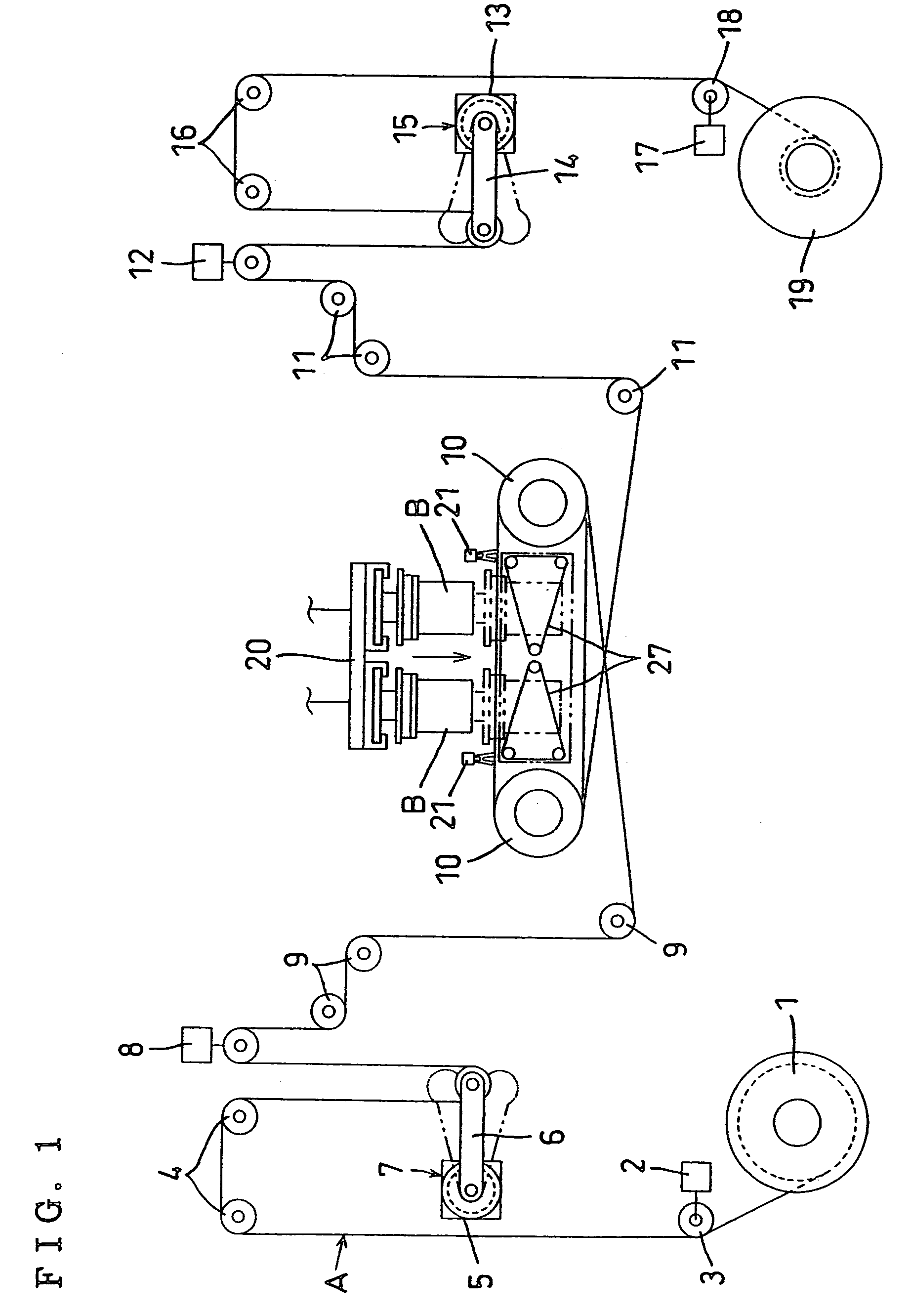
[0038]FIG. 1 shows the entire structure of a wire saw. A wire A drawn from a feed side real 1 is adapted to be introduced through a feed side traverser 3 to be driven by a motor 2, a tension mechanism 7 including an encoder 5 and a tension arm 6 via a plurality of guide pulleys 4, a load cell 8 for measuring the tension of the wire A and a plurality of guide pulleys 9; to form a wire array by winding numerous times across a pair of work rollers 10 juxtaposed on both sides at a predetermined interval; and thereafter, to be wound around a retrieving side reel 19 through a plurality of guide pulleys 11, another load cell 12 for measuring the tension of the wire A, another tension mechanism 15 including an encoder 13 and a tension arm 14, a plurality of guide pulleys 16, and another retrieving side traverser 18 to be driven by another motor 17.

[0039...


PUM

PropertyMeasurementUnit
thicknessaaaaaaaaaa
diameteraaaaaaaaaa
diameteraaaaaaaaaa

Abstract

In a cutting method by a wire saw, in which a wire A at a wire array wound around work rollers 10 is made to reciprocate or travel in one direction at a high speed and numerous pieces of wafers are cut out in abutment of a workpiece B against the wire array, a receiving member 27 of a cassette type having numerous support wires 34 arranged at the same pitch as that of the wire at the wire array is disposed at a position immediately under the wire array for cutting the workpiece B; and wafers b cut out of the workpiece B by the wire A are contained in separation one from another between the support wires 34 in the receiving member 27. Thus, the wafers can be prevented from adhering to each other during a cutting operation, thus to be accurately cut, and further, the wafers can be prevented from being cracked during the cutting operation, thus to be efficiently separated one from another, so as to enhance wafer cleansing performance.

Description

BACKGROUND OF THE INVENTION[0001]1. Field of the Invention[0002]The invention relates to a cutting method by a wire saw and a cut workpiece receiving member in a wire saw and, more particularly, to a method for separating cut workpieces one from another during a workpiece cutting operation by a wire saw and a receiving member for favorably receiving the cut workpieces in separation one from another.[0003]2. Description of the Related Art[0004]In a wire saw, a wire reeled out from a feed side real is introduced to a tension mechanism and a load cell for measuring tension via a traverser and a guide pulley; and then, is wound numerous times around at least two work rollers, thereby forming a wire array; and finally, is wound around a retrieving side reel.[0005]The above-described wire at the wire array across the work rollers is made to reciprocate or travel in one direction at a high speed, so that the workpiece is cut out into numerous wafers at the same time in abutment of the work...

Claims


Application Information

Patent Timeline
Patent Type & Authority Patents(United States)
IPC IPC(8): B28D1/08
CPCB28D5/0082Y10S269/909
Inventor MATSUDA, TAKEHARU
Owner TAKATORI
Why Eureka
Try Eureka