Pneumatic tire with electrically conductive cord extending between a bead portion and a tread portion of the tire

a pneumatic tire and electrically conductive cord technology, applied in the field of pneumatic rubber tires, can solve the problems of significantly reducing or even eliminating the aforesaid path of suitable electrical conductivity between the tires and and reducing the electrical conductivity of the sidewall layer of the tir

Inactive Publication Date: 2007-10-23
THE GOODYEAR TIRE & RUBBER CO
View PDF8 Cites 19 Cited by
  • Summary
  • Abstract
  • Description
  • Claims
  • Application Information

AI Technical Summary

Benefits of technology

[0098]Therefore, for example, such means of providing a path of reduced electrical resistivity is said thin rubber strip of a carbon black-rich rubber composition which contains at least 50 phr of carbon black positioned through, or around a portion of, the tread rubber cap layer to extend from a running surface of said tread cap layer to said carbon black-rich rubber tread base layer, wherein said rubber compositions of said individual tire bead component(s), said tire tread rubber base layer, said tire belt ply, and said thin rubber strip extending through or around said tread rubber cap layer contains a rubber reinforcing carbon black content in a sufficient amount that is above the carbon black percolation point to thereby make said rubber compositions relatively electrically conductive.

Problems solved by technology

However, such reduction in carbon black content in the outer sidewall layer can also significantly reduce the electrical conductivity of the tire sidewall layer, particularly if the carbon black content is reduced below its percolation point, which, in turn, can result in significantly reducing or even eliminating the aforesaid path of suitable electrical conductivity between the tire's bead region and the tire's tread region.

Method used


Image

  • Pneumatic tire with electrically conductive cord extending between a bead portion and a tread portion of the tire
  • Pneumatic tire with electrically conductive cord extending between a bead portion and a tread portion of the tire
  • Pneumatic tire with electrically conductive cord extending between a bead portion and a tread portion of the tire

Examples


example i

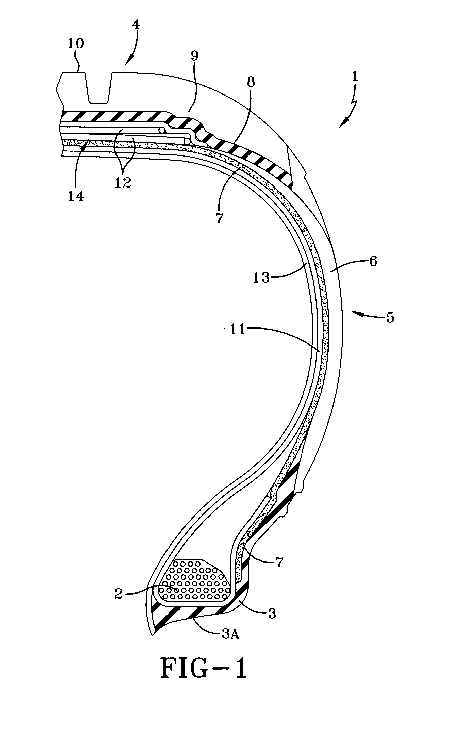
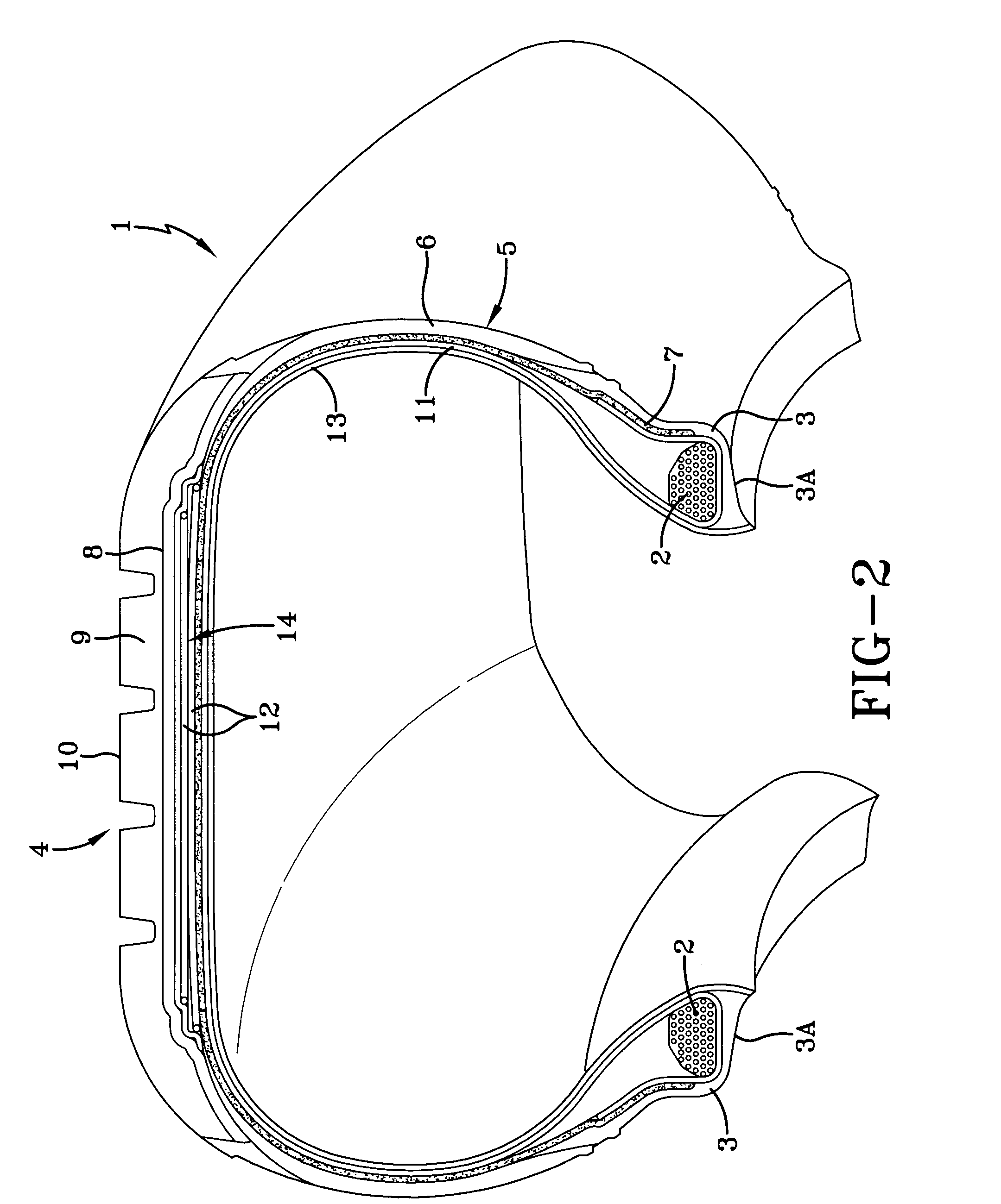
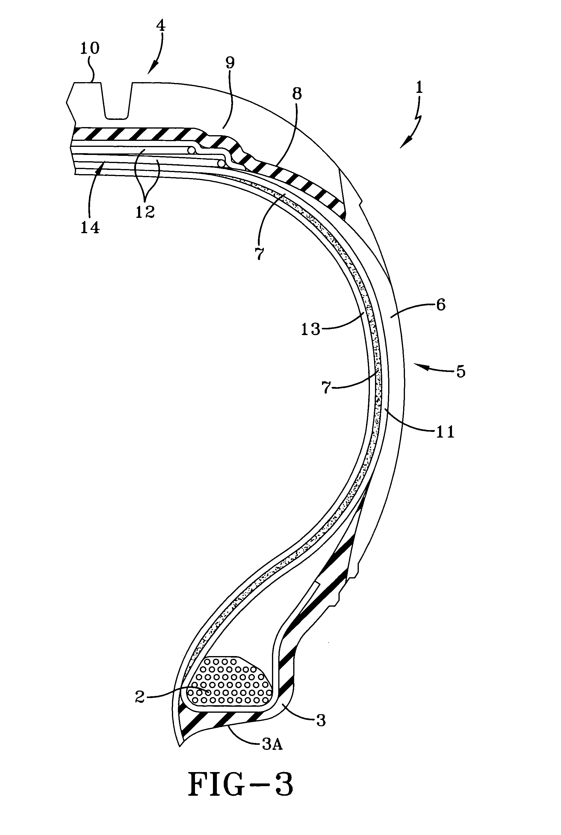
[0133]Tires of size P225 / 60R16 Eagle RS-A are prepared having treads of cap / base construction and constructed in a manner similar to FIG. 1 and FIG. 2 of the drawings insofar as the electrically relatively nonconductive rubber compositions of the carcass plies (11) and sidewall layer (6) are concerned, insofar as the electrically relatively conductive rubber compositions of the chafer component (3), with its tire mounting surface (3A), as well as the belt ply (12), tread base layer (8) and tread cap layer (9) are concerned.

[0134]Several spaced apart electrically conductive cords are placed to extend from bead-to-bead through the crown region of the tires. The electrically conductive cords are composed of a cord of polyester fibers, or filaments, around which was spirally (helically) wound a very thin stainless steel filament.

[0135]For a first tire, an electrically conductive cord (7) is positioned over a carcass ply (11), and thereby between the carcass ply (11) and rubber sidewall ...


PUM

PropertyMeasurementUnit
electrical resistanceaaaaaaaaaa
resistanceaaaaaaaaaa

Abstract

A pneumatic rubber tire containing at least one electrically conductive cord extending between its bead and tread portions to provide a path of least electrical resistance. The electrically conductive cord is comprised of at least one electrically conductive metal filament spirally wound around a centrally disposed core of at least one organic fiber. The electrically conductive cord does not extend to, and is exclusive of, an outer surface of the tire.

Description

[0001]This application claims the benefit of Provisional Application Ser. No. 60 / 513,738 filed Oct. 23, 2003.FIELD OF THE INVENTION[0002]This invention relates to a pneumatic rubber tire which contains at least one electrically conductive cord extending between its electrically conductive wheel-rim mounting surface rubber component and its electrically conductive tread base layer rubber component or one or more intermediate electrically conductive rubber components therebetween to provide a path of least electrical resistance between the tire wheel-rim mounting surface and the tire tread base layer. An electrically conductive path is thereby provided. The electrically conductive cord is comprised of at least one electrically conductive metal filament spirally wound around a centrally disposed core of at least one organic fiber. The electrically conductive cord does not extend to, and therefore is exclusive of, an outer surface of the tire. The electrically conductive cord may also b...

Claims


Application Information

Patent Timeline
Patent Type & Authority Patents(United States)
IPC IPC(8): B60C9/00B60C19/08B60C9/04H05F3/00B60C1/00B60C9/02C08K3/04
CPCB60C1/0016B60C1/0025B60C9/02B60C19/08C08K3/04B60C11/005B60C9/005C08L21/00Y10T152/10873C08K2201/001Y10S152/02
Inventor ZANZIG, DAVID JOHNRYBA, JENNIFER LYNBALDWIN, JR., DONALD WILLIAMPUTINSKI, MICHAEL EDWARDDHEUR, JEAN LUCDAUVISTER, PIERRE MARIE JEAN GUSTAVE GHISLAIN
Owner THE GOODYEAR TIRE & RUBBER CO
Why Eureka
Try Eureka