Harness routing structure

a routing structure and harness technology, applied in the direction of roofs, cables, insulated conductors, etc., can solve the problems of difficult layout of the harness routing, achieve the effect of guiding devices, increase the degree of freedom of routing configuration, and high efficiency

Active Publication Date: 2007-10-23
HONDA MOTOR CO LTD
View PDF16 Cites 88 Cited by
  • Summary
  • Abstract
  • Description
  • Claims
  • Application Information

AI Technical Summary

Benefits of technology

[0007]Thus, an object of the present invention is to provide a routing structure for harnesses in which the layout of the harness routing becomes simple.
[0012]According to the invention, due to the torsion-permitting portions for the harnesses that are provided in the installation portions at the end portions of the guiding device, the rotation of the end portions of the guiding device can be permitted, the degree of freedom of the routing configuration of the harnesses and the guiding device is increased, and thereby space-saving can be realized.
[0013]According to the invention, due to the torsion-permitting portion provided in both end portions of the guiding device, it is possible to increase the degree of freedom of the routing configuration of the harnesses along the entire guiding device.
[0014]According to the invention, the rotation of the end portions of the guiding device due to the movement of the sliding door in the horizontal direction can be converted into a twisting action with high efficiency.
[0015]According to the invention, it is possible to prevent damage to the harnesses because the occurrence of burrs in the direction that intersects the direction along the harnesses can be avoided during molding, and therefore, it is possible to improve the durability of the harnesses.

Problems solved by technology

However, because the curvature direction and the installation angle of the harness guide are restricted due to the ends of the harness guide being attached respectively to the sliding door and the vehicle body, there are problems in that it is necessary to secure by an equivalent amount a large routing area for the harness guide, in particular in the outward transverse direction of the vehicle, and in that the layout for the harness routing becomes difficult.

Method used


Image

  • Harness routing structure
  • Harness routing structure
  • Harness routing structure

Examples


Embodiment Construction

[0037]Next, an embodiment of the present invention will be explained with reference to the figures.

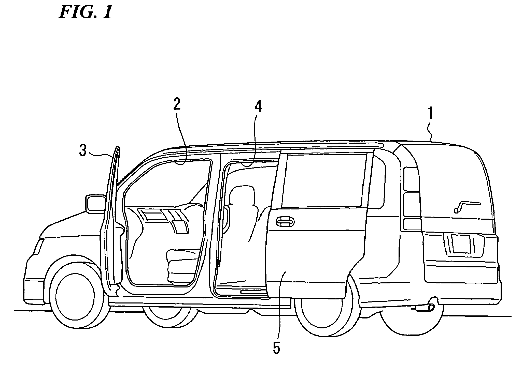
[0038]A so-called mini-van type vehicle is shown in FIG. 1. On the vehicle body 1 of this vehicle, front side doors 3 are supported as to be able to open and close in the front door installation opening portions 2 that are formed on both sides by the front seats. In addition, behind the front side door 3 on the passenger side, a sliding door 5 is provided in the back door installation opening portion 4 so as to be able to open and close in the longitudinal direction. This sliding door 5 is supported so as to slide freely on the vehicle body 1 by arms provided on the top portion, the center portion, and the bottom portion thereof, and the sliding door 5 is automatically opened and closed by a drive unit (not illustrated).

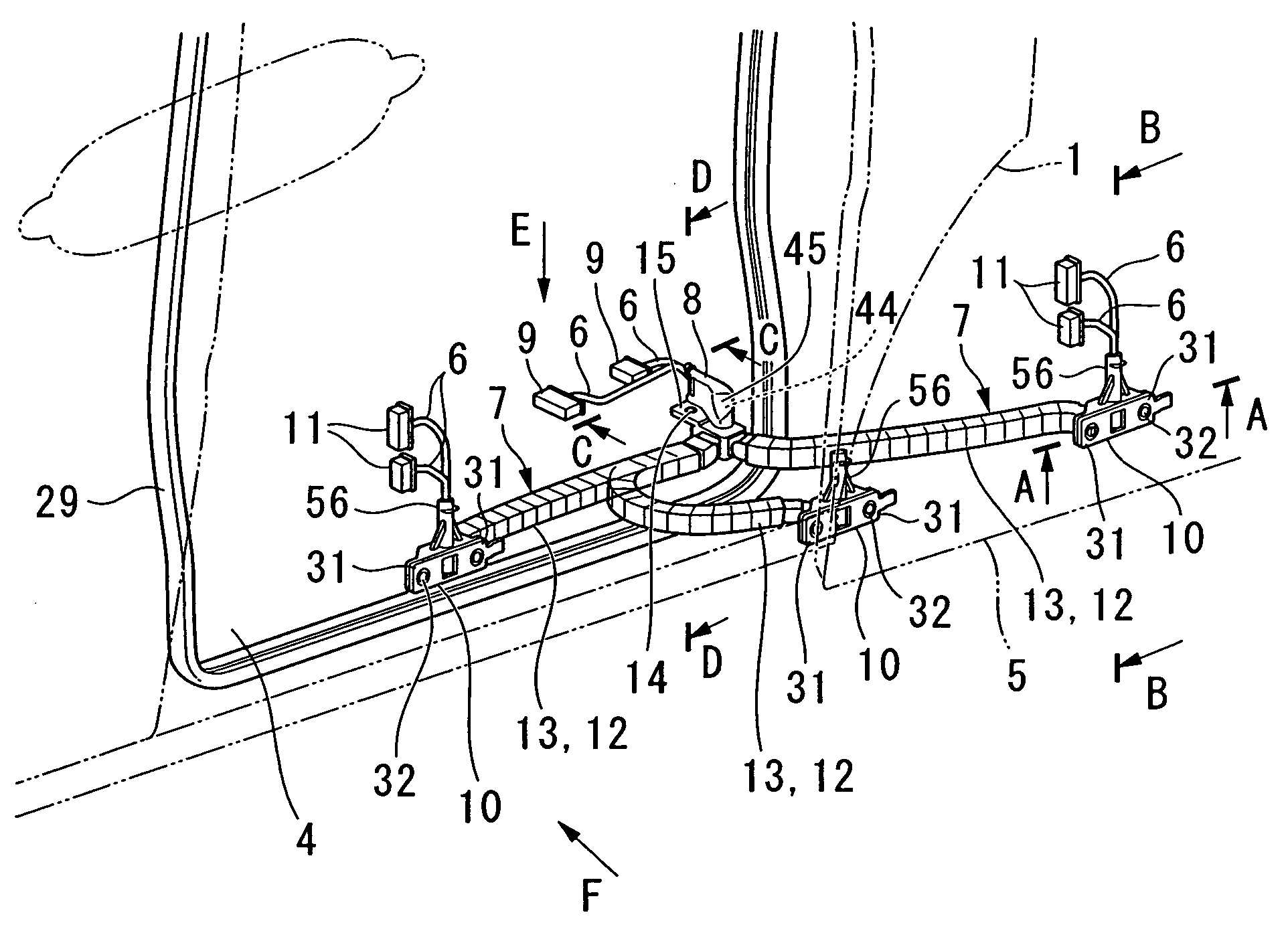
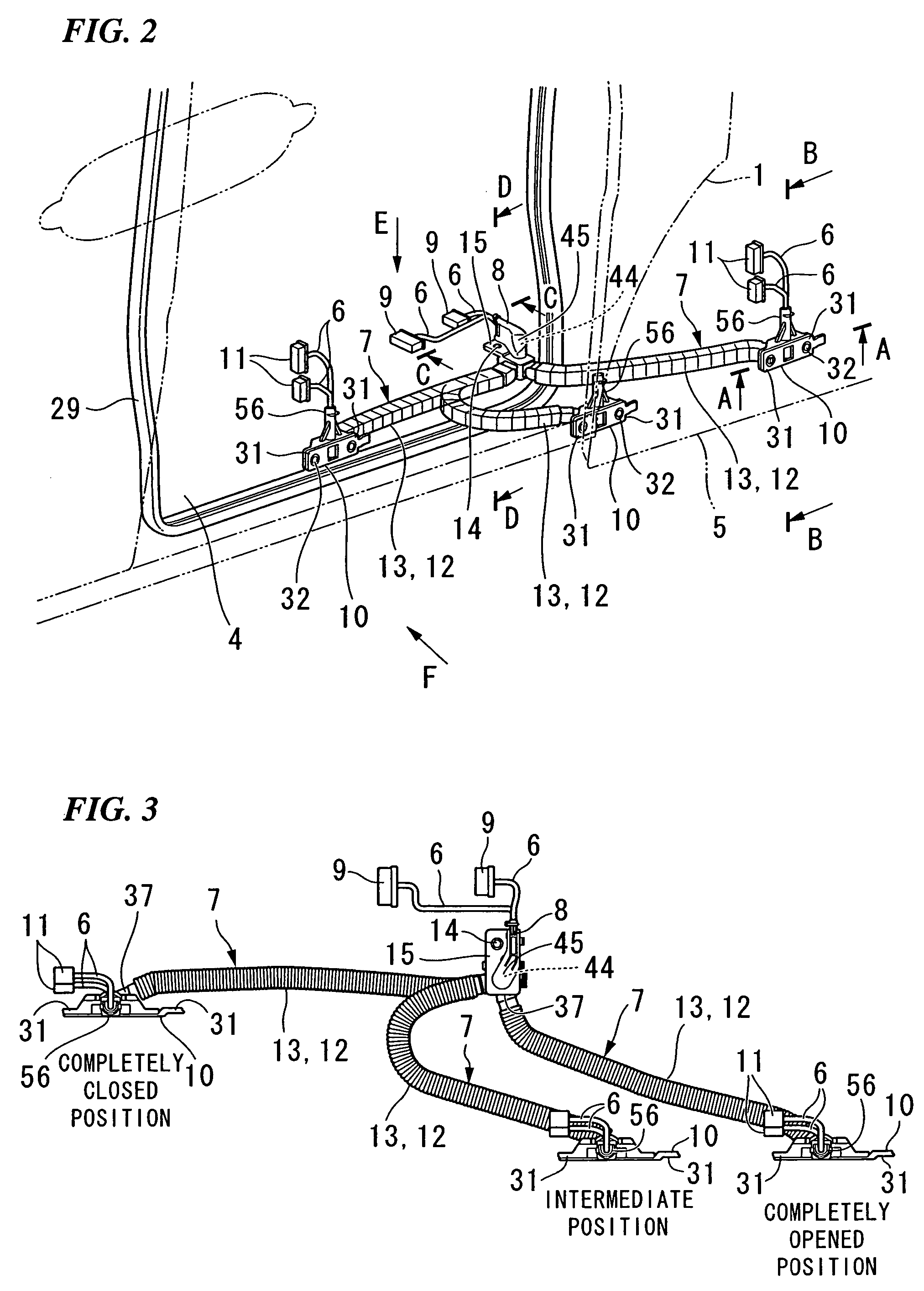
[0039]As shown in FIG. 2 and FIG. 3, between the sliding door 5 and the vehicle body 1, an electricity supply harness for the drive unit for opening and closing the sli...


PUM


Abstract

A harness routing structure for a sliding door includes harnesses that are routed between a vehicle body and a sliding door, and a guiding device that is provided along the harnesses and that guides the harnesses, wherein the guiding device has at the ends thereof installation portions that are respectively installed on the vehicle body and the sliding door, and a torsion-permitting portion for permitting twisting of the harnesses is provided along the harnesses in the installation portions.

Description

BACKGROUND OF THE INVENTION[0001]1. Field of the Invention[0002]The present invention relates to a harness routing structure that is used, for example, between a sliding door and a vehicle body of a vehicle such as an automobile or the like.[0003]Priority is claimed on Japanese Patent Application No. 2005-151372, filed May 24, 2005, the content of which is incorporated herein by reference.[0004]2. Description of Related Art[0005]In some vehicles equipped with a sliding door, the sliding door can be opened and closed by using electric power. In such a sliding door, harnesses for a power supply and sensors must be routed between the vehicle body and the sliding door. When routing the harnesses, the harnesses are protected by providing a harness guide that retains the harnesses. The harness guide is provided because the profile of the harnesses, or specifically, the routing configuration, changes as the sliding door is opened and closed (refer, for example, to Japanese Unexamined Paten...

Claims


Application Information

Patent Timeline
Patent Type & Authority Patents(United States)
IPC IPC(8): B60J5/06
CPCH02G3/0475
Inventor GOTOU, JOUJIADACHI, MASATOSHI
Owner HONDA MOTOR CO LTD
Why Eureka
Try Eureka