Extruder for continuously working and/or processing flowable materials

a technology of flowable materials and continuous working, which is applied in the direction of mixing/kneading with horizontally mounted tools, manufacturing tools, and food shaping, etc., can solve the problem of reducing the conveying properties in the area of the supply por

Active Publication Date: 2007-10-23
BLACH VERWALTUNGS GMBH
View PDF72 Cites 16 Cited by
  • Summary
  • Abstract
  • Description
  • Claims
  • Application Information

AI Technical Summary

Benefits of technology

[0018]After the product flow inhibiting element, the screw channel is largely empty. Accordingly, it is advantageous to dispose a flow inhibiting element before a degassing opening of the extruder, thereby preventing material from exiting through the degassing opening.
[0019]If the extruder has a plurality of supply ports for different material

Problems solved by technology

This improves the exchange of material between the outside and inside proces

Method used


Image

  • Extruder for continuously working and/or processing flowable materials
  • Extruder for continuously working and/or processing flowable materials
  • Extruder for continuously working and/or processing flowable materials

Examples


Embodiment Construction

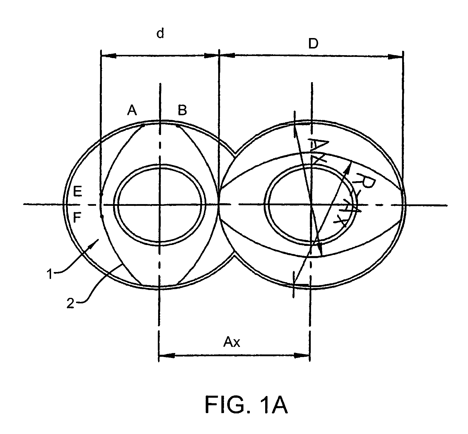
[0032]According to FIG. 1A, screw elements 1 have a transverse profile 2 composed of three circular arcs A-B, E-F and A-E. Circular arc A-B has a diameter corresponding to outside screw diameter D, circular arc E-F has a diameter corresponding to screw core diameter d, and circular arc A-E has a diameter whose radius corresponds to center distance Ax of the two screw elements 1.

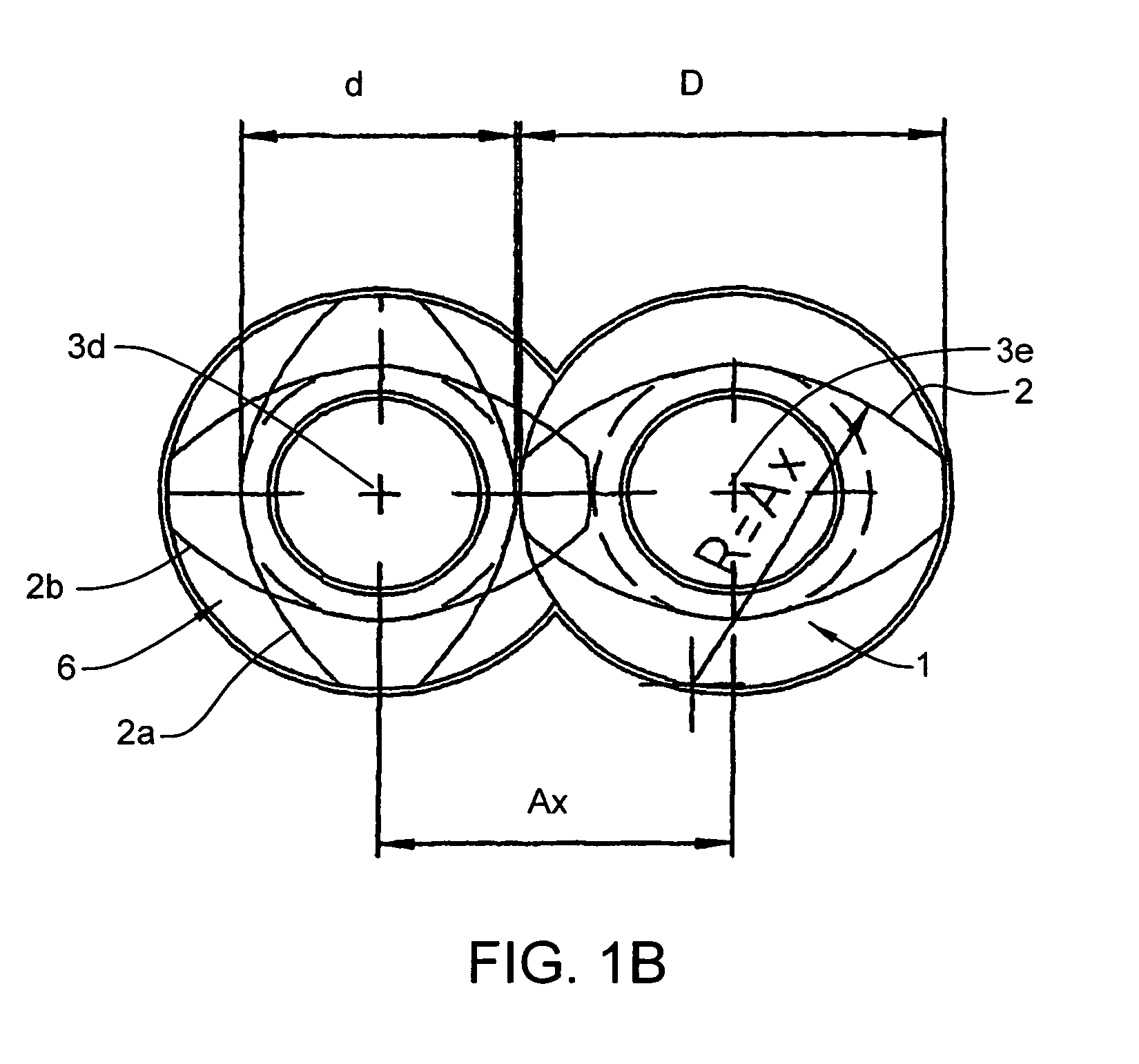
[0033]FIG. 1B shows a transverse profile 2 of screw element 1 that is in close mesh with profile 2a of passage screw element 6 having the two screw profiles 2a and 2b offset by 90°, as explained in more detail below in FIG. 2.

[0034]Accordingly, FIG. 2 shows five screw shafts 3a to 3e driven in the same direction, in a plane for clarity's sake. The conveying direction of the extruder is designated with arrow 4, and the direction of rotation of screw shafts 3a to 3e with arrow 5. Screw elements 1 on shafts 3a and 3e thus convey in direction 4 both in area A and in area B, while screw elements 1 conveying only i...


PUM

PropertyMeasurementUnit
Flow rateaaaaaaaaaa
Diameteraaaaaaaaaa
Speedaaaaaaaaaa

Abstract

An extruder has at least three parallel, co-rotating shafts disposed in a cavity therein along a circle. The shafts are equipped with screw elements closely intermeshing over their whole circumference. At least one screw element is formed as a passage screw element with recesses in the screw crest, screw core and/or screw flank. Downstream of a supply port an element is provided for inhibiting the product flow in the flight of the passage screw element. A degassing opening is located downstream and adjacent the inhibiting element.

Description

FIELD OF THE INVENTION[0001]This invention relates to an extruder for continuously working and / or processing flowable materials having co-rotating shafts parallel to the extruder axis and disposed in a cavity of an extruder housing.BACKGROUND OF THE INVENTION[0002]In co-rotating twin-shaft extruders equipped with double-flighted intermeshing screws, the total material flow is divided in the process space, i.e. the cavity in the extruder housing, into three parallel product flows extending along the screws and the inside wall of the extruder housing. The ratio of inside housing circumference to process space length is about 1:1.5 to 1:5. In contrast, in an extruder with e.g. twelve co-rotating parallel shafts disposed along a circle, i.e. forming a ring, the material flow is distributed over twelve axis-parallel product flows, and the ratio of inside housing circumference to process space length is between 3:1 and 1:1.5. Such an extruder is characterized by a substantially greater ci...

Claims


Application Information

Patent Timeline
IPC IPC(8): B29B7/48B29C47/42A21C1/02A21C1/06B01F7/08B29C48/405B29C48/425
CPCB29B7/485B29C47/0861B29C47/40B29C47/42B29C47/369B29C47/402B29C47/0009B29C48/03B29C48/2517B29C48/39B29C48/402B29C48/425B29C48/435B29C48/43B29C48/405
Inventor BLACH, JOSEF A.
Owner BLACH VERWALTUNGS GMBH
Why Eureka
Try Eureka