Apparatus and method for detecting deterioration of exhaust gas sensor

a technology of exhaust gas sensor and detector, which is applied in the direction of electrical control, instruments, material electrochemical variables, etc., can solve the disadvantages of deterioration, disadvantages of detecting actual progressing degree of deterioration, and low degree of accuracy in estimation

Inactive Publication Date: 2007-10-23
DENSO CORP
View PDF4 Cites 27 Cited by
  • Summary
  • Abstract
  • Description
  • Claims
  • Application Information

AI Technical Summary

Problems solved by technology

Deterioration of the exhaust gas sensor may degrade of a degree of accuracy in detection performance of the exhaust gas sensor so that this may degrade efficiency in purifying the exhaust gas.
Thus, an actual progressing degree of the deterioration is disadvantageously not detected.
However, in the deterioration diagnosis method in Japanese Unexamined Patent Publication No.
Therefore, a degree of accuracy in estimation may disadvantageously become low and also a degree of accuracy in diagnosing the deterioration may disadvantageously become low.

Method used


Image

  • Apparatus and method for detecting deterioration of exhaust gas sensor
  • Apparatus and method for detecting deterioration of exhaust gas sensor
  • Apparatus and method for detecting deterioration of exhaust gas sensor

Examples


Embodiment Construction

[0021]An embodiment that embodies a best mode for carrying out the present invention will be described.

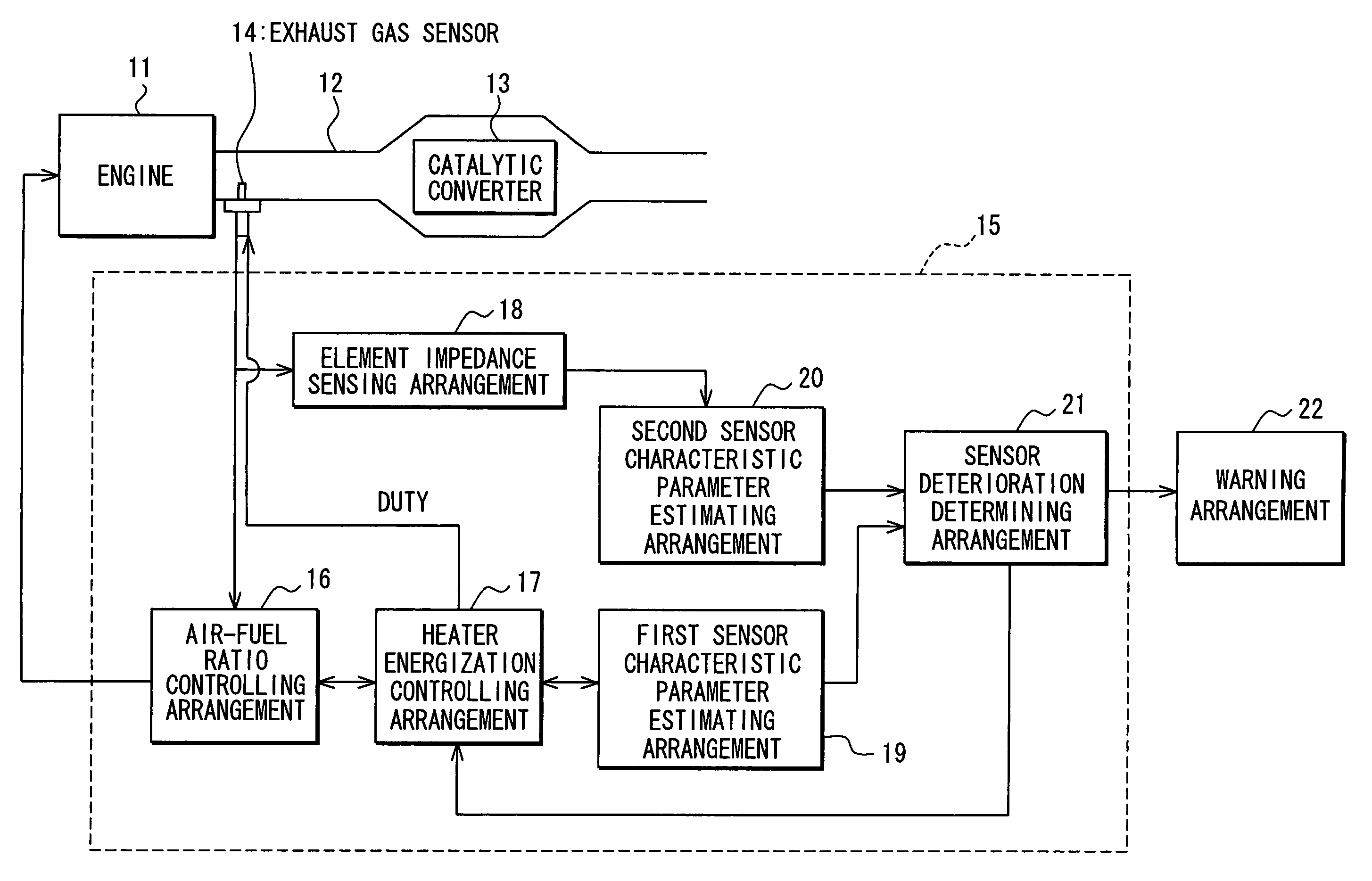
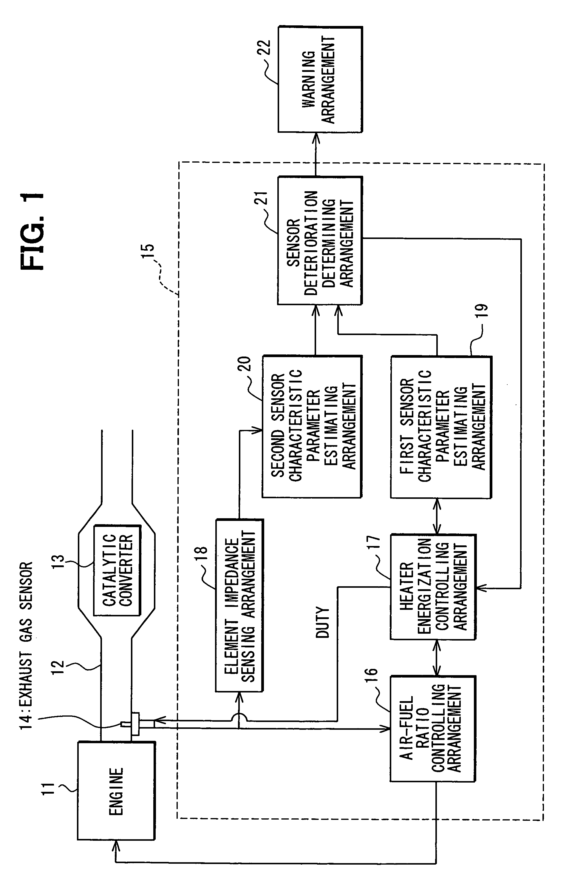
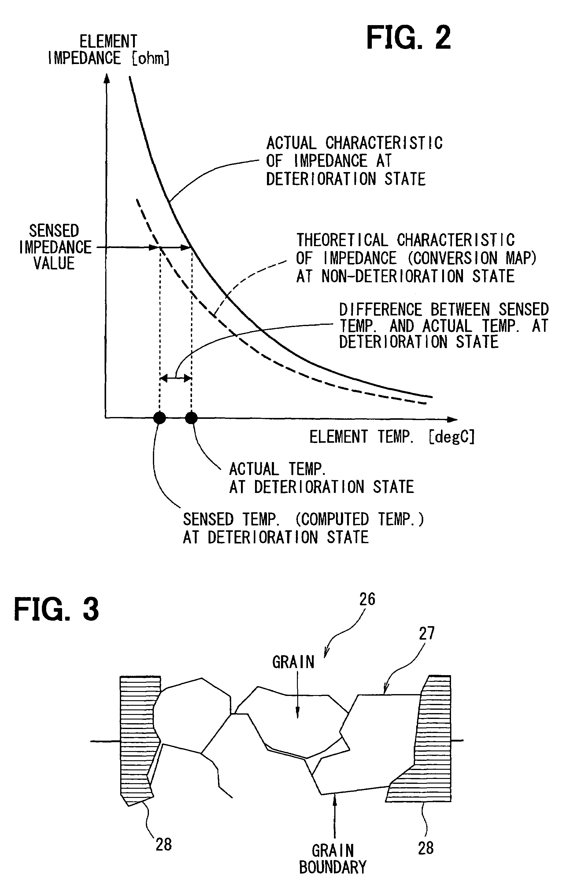
[0022]Firstly, a schematic structure of an entire system will be described. As shown in FIG. 1, an exhaust gas pipe 12 of an engine 11, which is an internal combustion engine, is provided with a catalytic converter 13, such as a three-way catalytic converter that reduces CO, HC and NOx in exhaust gas. An exhaust gas sensor 14, such as an oxygen sensor and an air-fuel sensor (A / F sensor), is provided on an upper stream side of the catalytic converter 13 for sensing one of a concentration of a gas component, an air-fuel ratio and an air-fuel mixture condition (rich or lean). Here, the concentration of the gas component includes an oxygen concentration in the exhaust gas. The exhaust gas sensor 14 includes a sensor element 26 (see FIG. 3), which is, for example, structured in such a manner that electrodes 28 adhere both sides of a zirconia solid electrolyte 27 for obtaining an output....


PUM

PropertyMeasurementUnit
thermal energyaaaaaaaaaa
sensing impedanceaaaaaaaaaa
impedanceaaaaaaaaaa

Abstract

A deterioration detecting apparatus for an exhaust gas sensor of an internal combustion engine, the exhaust gas sensor including a sensor element and a heater that heats the sensor element, computes a first sensor characteristic parameter, which is related to a characteristic of the sensor element, by estimating an interchange state of thermal energy between the sensor element and a periphery of the sensor element. The deterioration detecting apparatus senses impedance of the sensor element. The deterioration detecting apparatus computes a second sensor characteristic parameter, which is related to the characteristic of the sensor element, based on the sensed impedance. The deterioration detecting apparatus determines a degree of deterioration of the exhaust gas sensor by comparing the first sensor characteristic parameter and the second sensor characteristic parameter.

Description

CROSS REFERENCE TO RELATED APPLICATION[0001]This application is based on and incorporates herein by reference Japanese Patent Application No. 2005-195633 filed on Jul. 5, 2005.BACKGROUND OF THE INVENTION[0002]1. Field of the Invention[0003]The present invention relates to a deterioration detecting apparatus for an exhaust gas sensor, the deterioration detecting apparatus diagnosing deterioration of the exhaust gas sensor, which is provided with a heater for heating a sensor element.[0004]2. Description of Related Art[0005]A recent vehicle is provided with an exhaust gas sensor (e.g., an air-fuel sensor, an oxygen sensor) on an exhaust gas pipe such that a feedback control of the air-fuel ratio is performed based on an output of the exhaust gas sensor in order to effectively purify exhaust gas by use of a catalyst. The exhaust gas sensor may not accurately sense the air-fuel ratio in a state where a temperature of the sensor element is equal to or less than an activation temperature....

Claims


Application Information

Patent Timeline
Patent Type & Authority Patents(United States)
IPC IPC(8): G06F19/00F02D41/14G01N27/26G01N27/41
CPCF01N11/00F01N11/007F02D41/1494F02D41/1495F02D41/1454F02D41/123F02D41/1446Y02T10/47F02D2041/228F02D2200/501Y02T10/40
Inventor GOTOH, YOSHIYUKIIIDA, HISASHITASHIRO, HIROSHI
Owner DENSO CORP
Why Eureka
Try Eureka