Apparatus for producing a visible line of light on a surface, particularly a wall

a technology of visible lines and apparatus, applied in the field of hand tools, can solve the problems of poor beam projection effect of level beams on floors or walls, and the inability to efficiently use laser diode light, and achieve the effect of convenient holding of the unit and high visible

Inactive Publication Date: 2007-10-30
TRIMBLE NAVIGATION LTD
View PDF9 Cites 37 Cited by
  • Summary
  • Abstract
  • Description
  • Claims
  • Application Information

AI Technical Summary

Benefits of technology

[0005]This invention allows the user to project a highly visible line on a surface. In addition it allows the line to be adjusted to true vertical or horizontal with the aid of a level vial when used on a vertical surface, e.g. a wall. An attachment to a stud-finder instrument is further provided. In some cases a magnet facilitates holding the unit to metal studs. The instrument is partially described in Disclosure Document No. 476310.

Problems solved by technology

Although indicating level, these levels do a poor job of projecting a beam on a floor or wall.
This is not a very efficient use of the laser diode light because of the natural divergence of the diode and cropping of the beam in collimation.

Method used


Image

  • Apparatus for producing a visible line of light on a surface, particularly a wall
  • Apparatus for producing a visible line of light on a surface, particularly a wall
  • Apparatus for producing a visible line of light on a surface, particularly a wall

Examples


Embodiment Construction

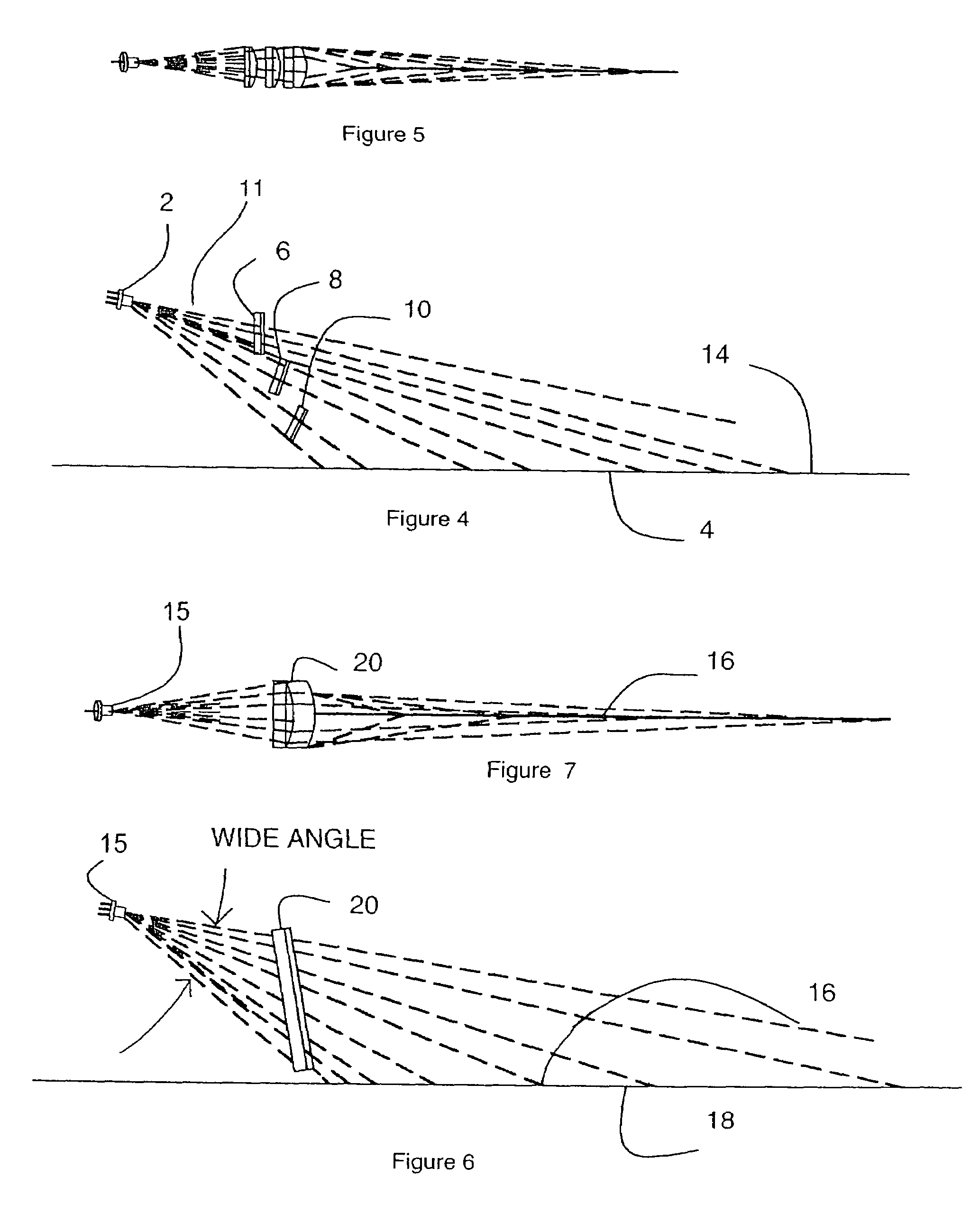
[0020]An optical system is shown in FIGS. 4 and 5. A laser diode 2 is positioned above a surface 4 to be marked, with the wide divergence angle of the laser, i.e. the major or long axis, perpendicular to the surface. In other words, a plane which is longitudinal relative to the laser diode and which includes the long axis of the beam is perpendicular to the surface. Cylinder lenses 6, 8, 10 project a beam 11 from the laser diode 2 onto a continuous line 14. The widths of the lenses are chosen to collect all the light from the narrow divergence angle (short axis) of the diode, substantially without cropping. The use of a plurality of lenses in the direction of the wide divergence (long axis) allows most of the light to be collected making the system efficient. The ability of each lens to be adjusted for a particular distance to produce a fine line is superior to the prior art; focus adjustment for distance can be done either by use of different focal length lenses or by adjustment of...


PUM


Abstract

An apparatus and method for efficiently generating a visible line of light on a surface such as a wall or a floor for the purpose of facilitating the layout process used in construction. Reference marking elements on the instrument correspond to the light beam's position. One or more level vials may be included for indicating vertical and horizontal, as well as a magnet for mounting and a reference bracket for a stud-finder instrument. In one embodiment the instrument is self-leveling on one axis only and is useful for projecting one or more orthogonal lines on a wall surface. The instrument, self-leveling or not, can be combined with a stud finder.

Description

BACKGROUND OF THE INVENTION[0001]This application is a continuation-in-part of application Ser. No. 10 / 338,764, filed Jan. 7, 2003, now abandoned, which was a continuation of application Ser. No. 09 / 684,696 filed Oct. 4, 2000, now U.S. Pat. No. 6,502,319.[0002]This invention relates to hand tools, and in particular the invention is concerned with a hand tool for projecting a reference beam of visible light for precise alignment on floors and walls.[0003]For some time laser beams have been used in construction for level references, vertical references and layout on floors and walls. Typically a construction worker marks the floor or walls indicating the location of walls, windows, or other building elements to be constructed. A chalk line is often used to permanently mark the walls or floors. This is a two man job with one man holding one end of the chalked string while the other snaps it, releasing chalk dust which makes the mark.[0004]The most common prior laser device is a simple ...

Claims


Application Information

Patent Timeline
Patent Type & Authority Patents(United States)
IPC IPC(8): G01C15/02B43L13/00G01B11/26
CPCG01C15/008G02B27/20G01C15/12Y10S33/21
Inventor GOODRICH, GARY
Owner TRIMBLE NAVIGATION LTD
Why Eureka
Try Eureka