
Blunt tip turbine blade

a turbine blade and blade technology, applied in the field of gas turbine engines, can solve the problems of increasing the difficulty of tip cooling during operation, oxidation of the blade tip, and particularly difficult cooling of the blade tip, and achieve the effect of improving the cooling effect of the tip

Active Publication Date: 2007-10-30
GENERAL ELECTRIC CO
View PDF22 Cites 13 Cited by
  • Summary
  • Abstract
  • Description
  • Claims
  • Application Information

AI Technical Summary

Benefits of technology

"The patent describes a turbine airfoil with pressure and suction sides. It extends from a root to an outer tip cap and has a flute that runs along its pressure sidewall. The technical effect of this design is improved airflow and better cooling of the airfoil, which leads to better performance and durability."

Problems solved by technology

The blade tip is particularly difficult to cool since it is exposed to the hot combustion gases on both the pressure and suction sides of the airfoil between the leading and trailing edges, as well as over the tip itself in the tip-shroud gap.
The tip floor defines the outer boundary for the internal cooling circuits of the airfoil, and positions the squealer ribs externally thereof which further increases the difficulty of tip cooling during operation.
Accordingly, turbine blade tips are subject to oxidation over extended use in the engine, and may require corresponding repair during maintenance outages of the engine.
Oxidation damage to the blade tip commonly limits the useful life of the blade during operation, as well as decreases turbine efficiency as the blade tips oxidize and wear during operation and correspondingly increase the blade tip clearance.
However, since the blade tips are subject to occasional tip rubbing with the surrounding turbine shroud, the squealer ribs are subject to abrasion wear which affects both efficiency of blade tip performance, and effectiveness of the tip shelf cooling.

Method used


Image

  • Blunt tip turbine blade
  • Blunt tip turbine blade
  • Blunt tip turbine blade

Examples


Embodiment Construction

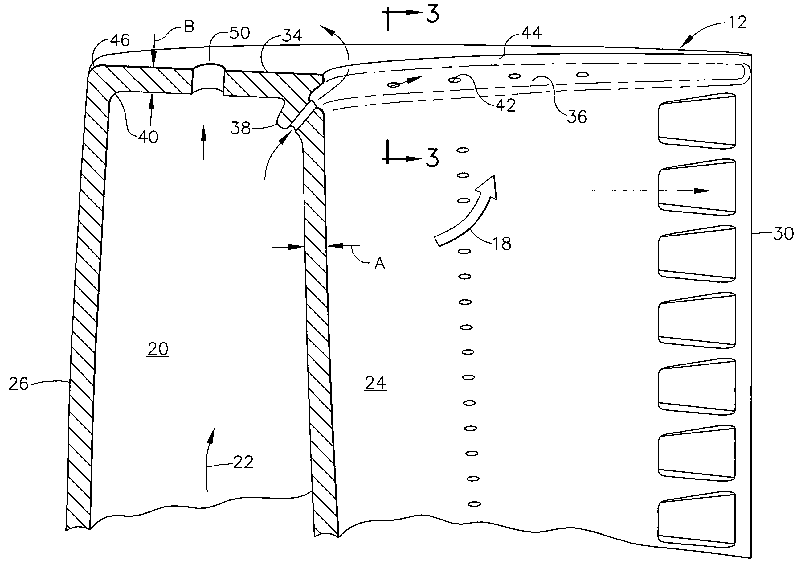
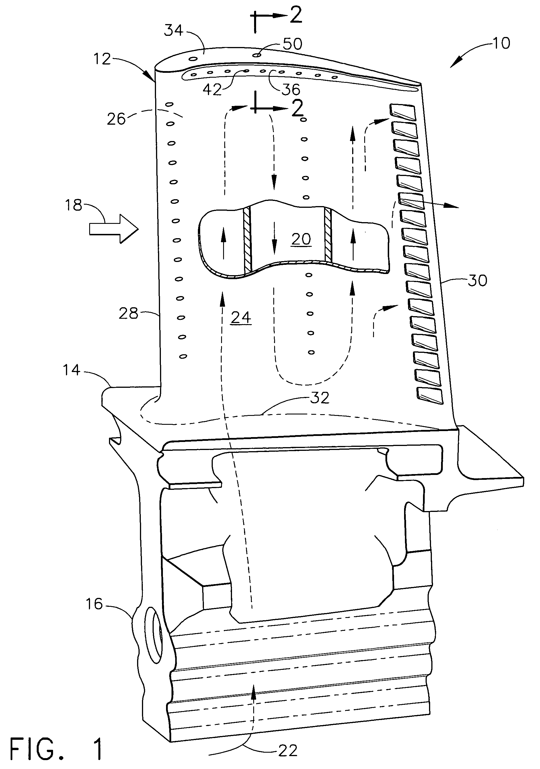
[0019]Illustrated in FIG. 1 is a turbine rotor blade 10 for a gas turbine engine. The blade includes a hollow airfoil 12 integrally joined in turn to a radially inner platform 14 and dovetail 16. The exemplary dovetail is an axial entry dovetail with multiple tangs or lobes supported in a complementary dovetail slot in the perimeter of a rotor disk (not shown).

[0020]A full row of the turbine blades 10 extends radially outwardly from the supporting rotor disk and receives combustion gases 18 from an upstream combustor (not shown) for extracting energy therefrom to power the engine compressor (not shown) during operation.

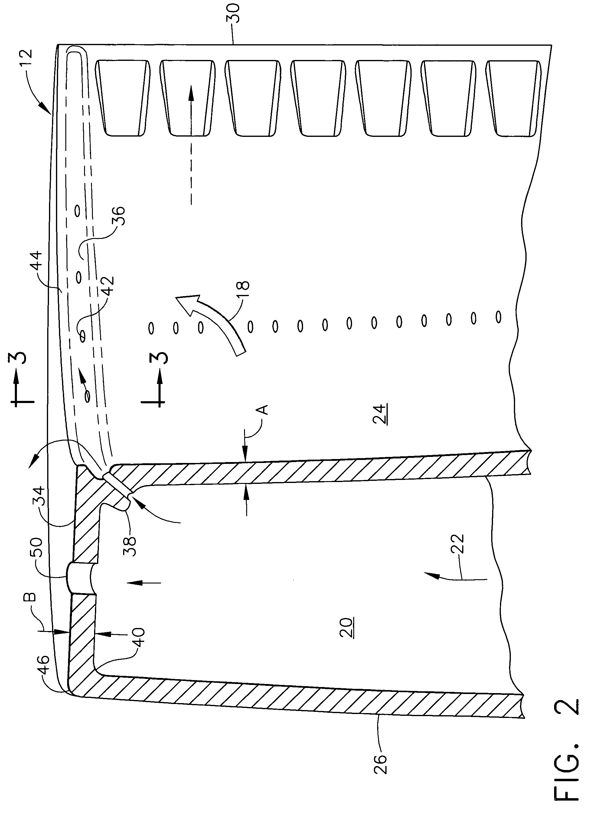
[0021]The hollow airfoil includes an internal cooling circuit 20 therein which receives cooling air 22 bled from the compressor during operation through an inlet channel in the dovetail. The cooling circuit may have any conventional configuration, such as the three-pass serpentine cooling circuit illustrated, with suitable inlet and outlet holes. The circuit typically...


PUM


Abstract

A turbine airfoil includes opposite pressure and suction sidewalls, and extends in chord between opposite leading and trailing edges and in span from a root to an outer tip cap. The tip cap bridges the sidewalls, and a flute extends chordally along the pressure sidewall and below the tip cap.

Description

BACKGROUND OF THE INVENTION[0001]The present invention relates generally to gas turbine engines, and, more specifically, to turbine blade cooling.[0002]In a gas turbine engine air is pressurized in a compressor and mixed with fuel in a combustor for generating hot combustion gases. Energy is extracted from the gases in several turbine stages which power the compressor and produce useful work such as powering an upstream fan in a turbofan aircraft engine application.[0003]Each turbine stage includes a stationary turbine nozzle which directs the combustion gases through a corresponding row of turbine rotor blades extending radially outwardly from a supporting rotor disk.[0004]The stator vanes and rotor blades include hollow airfoils with internal cooling circuits therein which use air bled from the compressor for cooling thereof during operation. Each stage of vanes and blades is configured differently for maximizing energy extraction from the combustion gases as they flow downstream ...

Claims


Application Information

Patent Timeline
Patent Type & Authority Patents(United States)
IPC IPC(8): F01D5/18F01D5/20
CPCF01D5/20F05D2250/292F05D2250/29Y02T50/673Y02T50/60
Inventor LEE, CHING-PANGWADIA, ASPI RUSTOMBRAUER, JOHN CHRISTOPHER
Owner GENERAL ELECTRIC CO
Learn More