Evanescent waveguide apparatus and method for measurement of dielectric constant

a waveguide and dielectric constant technology, applied in the field of waveguides, can solve the problems of not providing an apparatus, not sufficiently informative methods, never being obtained or available in the prior period, etc., and achieve the effects of reducing cross-sectional area, reducing width, and small sampl

Active Publication Date: 2007-10-30
NAVY UNITED STATES OF AMERICA ASREPRESENTED BY THE DEPT OF THE
View PDF10 Cites 10 Cited by
  • Summary
  • Abstract
  • Description
  • Claims
  • Application Information

AI Technical Summary

Benefits of technology

[0016]An advantage of the present invention is that a very small sample may be utilized.
[0017]Another advantage of the present invention is that the method does not require a shielded or anechoic environment.
[0018]A feature of the present invention is a split waveguide having a reduced cross-sectional area in a middle portion thereof.
[0019]These and other objects, features, and advantages of the present invention will become apparent from the drawings, the descriptions given herein, and the appended claims. However, it will be understood that above listed objects and advantages of the invention are intended only as an aid in understanding aspects of the invention, are not intended to limit the invention in any way, and do not form a comprehensive list of objects, features, and advantages.
[0020]Accordingly, the present invention provides an apparatus for measuring a dielectric constant of an unknown material that may comprise one or more elements such as, for example, a waveguide frame that defines a rectangular cross-section waveguide aperture there through. The waveguide frame comprises a first end on one side of the waveguide aperture and a second end on an opposite side of the waveguide aperture. The first end and the second end define the waveguide aperture with a width a and a height b wherein the width a is greater than the height b. The waveguide frame is split along a length of the waveguide to permit the waveguide frame to be opened and closed. The waveguide frame has a middle section with at least one reduced waveguide aperture portion comprising a reduced width less than the width a. At least one sample of the unknown material is utilized and has a width equal to the reduced width a and height b to thereby mate with the reduced waveguide aperture portion. The at least one sample of unknown material is insertable into the middle section when the waveguide frame is opened and then mates to the reduced waveguide aperture portion when the waveguide frame is closed to permit measurement of the dielectric constant of the sample of unknown material.
[0021]In one embodiment, the apparatus may further comprise a metal septum insertable into the middle section of the waveguide frame for dividing the waveguide width a into one-half whereby the reduced waveguide aperture portion actually comprises two reduced waveguide aperture portions. For this embodiment, two samples of the unknown material are insertable on opposite sides of the metal septum. The metal septum may be comprised of brass. The metal septum has a septum length, and the two samples may preferably have a length equal to the septum length.

Problems solved by technology

This method may not be sufficiently informative when the material is to be used for RF applications because for most materials, the static (f=0 Hz) dielectric constant is different from that seen by a RF signal.
The above cited prior art does not provide an apparatus and method utilizing an air-filled metallic waveguide fitted with a metal (e.g. brass) septum or plate that divides the waveguide in half for a portion of its length whereby the material to be measured is fitted in the waveguide on either side of the metal sheet.
The solutions to the above-described problems are highly desirable but have never been obtained or available in the prior art.

Method used


Image

  • Evanescent waveguide apparatus and method for measurement of dielectric constant
  • Evanescent waveguide apparatus and method for measurement of dielectric constant
  • Evanescent waveguide apparatus and method for measurement of dielectric constant

Examples


Embodiment Construction

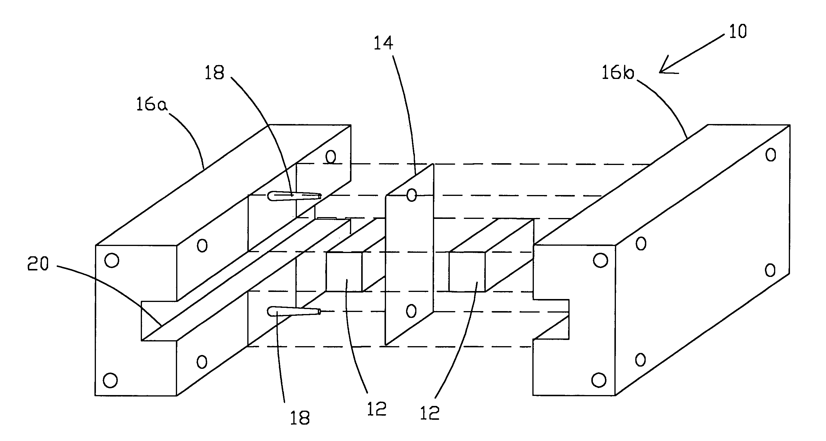
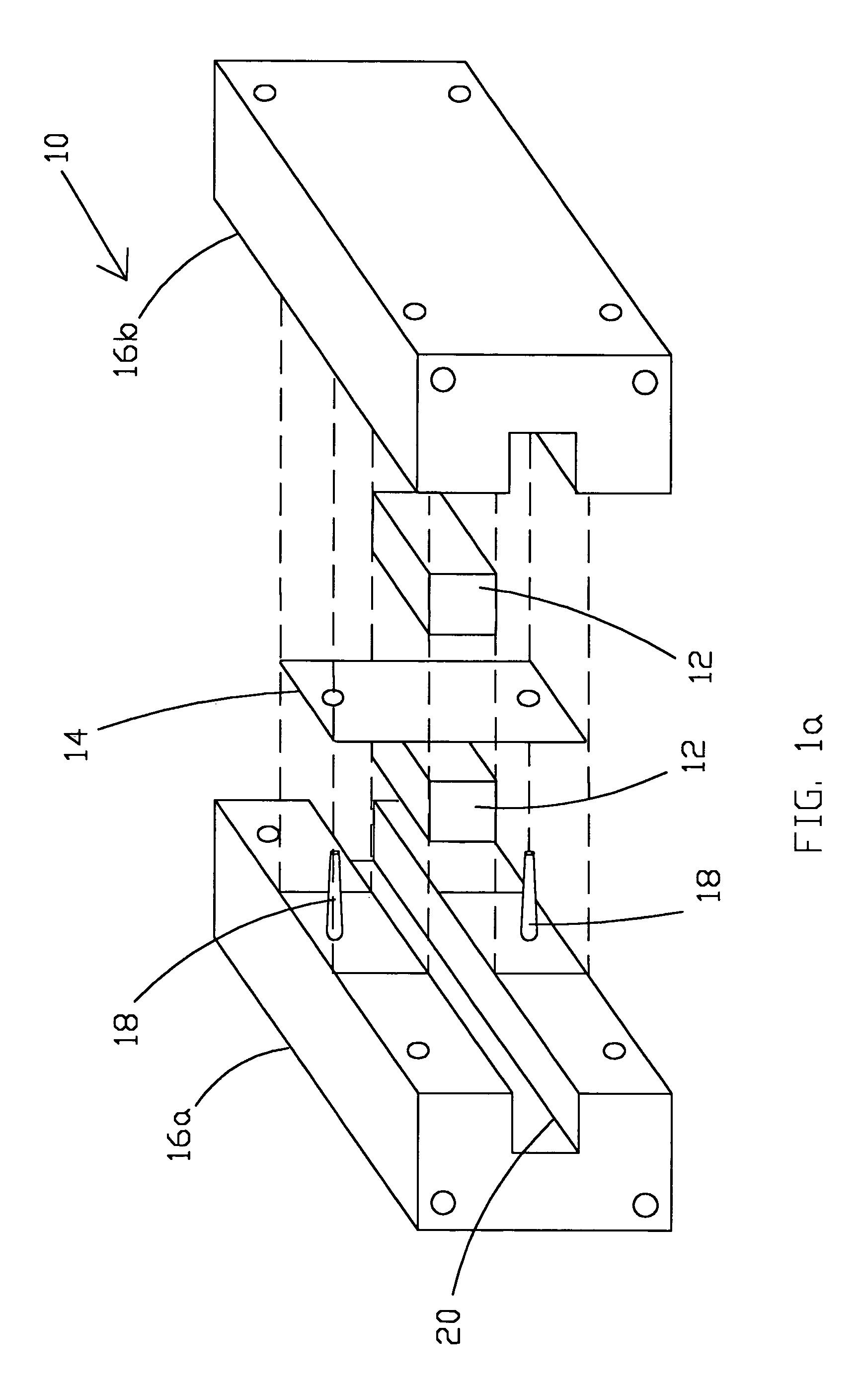
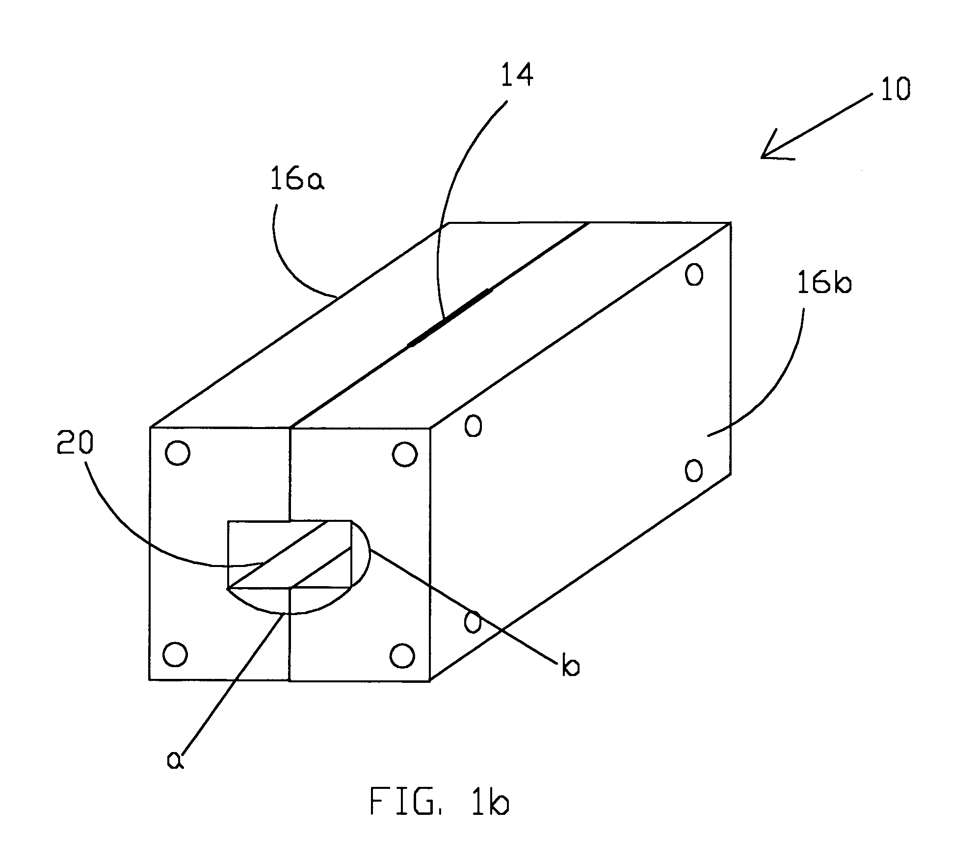
[0033]The present invention provides a tool for measuring the dynamic (as opposed to static) dielectric constant of an unknown material in the microwave regime by using only a small sample placed in a cutoff section of a preferably rectangular waveguide. Only a very small sample of the unknown material is required. Because the measurement can take place without the need to build a shielded or anechoic environment, the cost and effort involved in measuring the dielectric constant is reduced.

[0034]It is well known from microwave theory that rectangular waveguides have a lower cutoff frequency below which they cannot propagate a real energy flow. This lowest order cutoff is determined by the width of the waveguide so long as the width, a, is at least twice the height, b:

[0035]fc=c2⁢a⁢ɛr(1)

where c is the velocity of light (3×10⁸ m / s), a is the width of the waveguide in meters, andεr is the dielectric constant of the material filling the waveguide. Above this cutoff frequency, the wavegu...


PUM


Abstract

A dielectric constant waveguide measuring apparatus preferably comprises a rectangular waveguide aperture on each end with a width a and height b. The waveguide frame is preferably split to permit the waveguide to be opened for insertion of the unknown material into a middle reduced cross-sectional area portion of the waveguide frame. In one embodiment, a metal septum is inserted between two samples of the unknown material to thereby reduce the cross-sectional area of the waveguide aperture by splitting width a of the rectangular waveguide in half. The waveguide frame is closed and a frequency response of the waveguide is then measured. The dynamic dielectric constant of the unknown material is determined from the frequency of the lowest order minimum value of the frequency response of the waveguide apparatus wherein the unknown material has been inserted.

Description

STATEMENT OF GOVERNMENT INTEREST[0001]The invention described herein may be manufactured and used by or for the Government of the United States of America for governmental purposes without the payment of any royalties thereon or therefore.BACKGROUND OF THE INVENTION[0002](1) Field of the Invention[0003]The present invention relates generally to measuring the dielectric constant of an unknown material and, more specifically, to a waveguide apparatus and method to thereby determine the dielectric constant.[0004](2) Description of the Prior Art[0005]The dielectric constant of a material is an essential parameter that is important to know with confidence when doing electromagnetics work. This parameter, denoted εr, may be utilized to determine the wave number of an electromagnetic wave in a material and as a result, the phase velocity, guided wavelength, and so forth, of the electromagnetic wave.[0006]Current methods for measuring the static dielectric constant include plating two oppos...

Claims


Application Information

Patent Timeline
Patent Type & Authority Patents(United States)
IPC IPC(8): G01R27/26G01R27/04H01P5/12
CPCG01R27/2664
Inventor TONN, DAVID A.
Owner NAVY UNITED STATES OF AMERICA ASREPRESENTED BY THE DEPT OF THE
Why Eureka
Try Eureka