Interferometer apparatus and method of processing a substrate having an optical surface

a technology of interferometer and optical surface, which is applied in the direction of interferometer, measurement device, instrument, etc., can solve the problems of insufficient quality of manufactured optical components, insufficient measurement accuracy, and inability to achieve the conventional interferometric apparatus and method. achieve the effect of improving the measurement of optical surfaces

Inactive Publication Date: 2007-10-30
CARL ZEISS SMT GMBH
View PDF15 Cites 17 Cited by
  • Summary
  • Abstract
  • Description
  • Claims
  • Application Information

AI Technical Summary

Benefits of technology

[0018]It is an object of the present invention to provide an interfer...

Problems solved by technology

It has been found that results achieved with the conventional interferometric apparatus and method are not completely satisfactory, in particular when the optical surface to be measured has a relatively strong curvature, i.e. a lower modulus of the radius of curvature (curvature=1/radius)....

Method used


Image

  • Interferometer apparatus and method of processing a substrate having an optical surface
  • Interferometer apparatus and method of processing a substrate having an optical surface
  • Interferometer apparatus and method of processing a substrate having an optical surface

Examples


Embodiment Construction

[0057]In the embodiments described below, components with are identical in function and structure are designated as far as possible by the same reference numerals. Therefore, to understand the features of the individual components of a specific embodiment, the descriptions of other embodiments should be referred to.

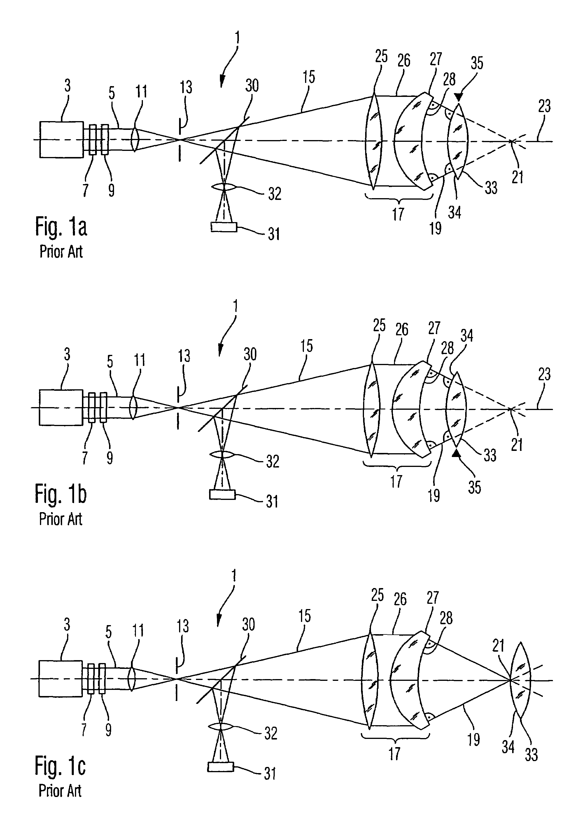
[0058]A drawback of the conventional method illustrated above with reference to FIG. 1 will now be illustrated with reference to FIGS. 2 and 3. It is to be noted that the illustrated prior art method is just one suitable example for illustrating such drawbacks resulting from polarization effects in the beam of the measuring light.

[0059]The invention obviating such drawbacks is, however, not limited to the apparatus and method illustrated in FIG. 1 and may be applied to any interferometer apparatus and method.

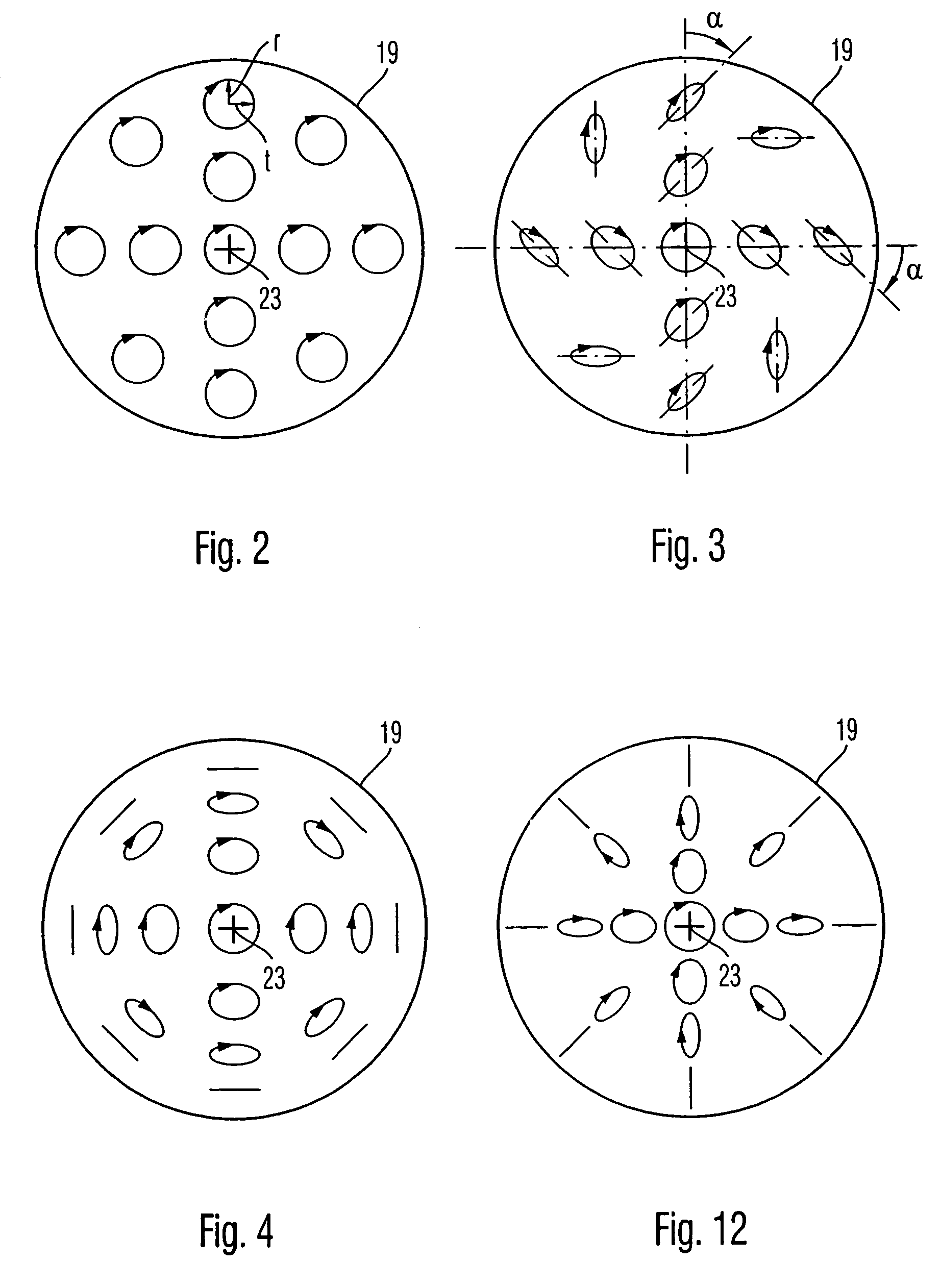
[0060]FIG. 2 shows a distribution of polarization states of the light of beam 15, 26, 19 of measuring light in FIG. 1c before the beam is incident on mirror 34 positi...


PUM


Abstract

A method of processing a substrate having an optical surface includes using an interferometer which includes optics for providing a beam of measuring light. The optics polarize the beam of measuring light such that a tangential polarization component continuously increases relative to a radial polarization component with increasing distance from an optical axis. The substrate is positioned in the beam of measuring light. Using the system, the interferometer determines a surface map of the optical surface, and determines deviations of the optical surface from a target shape.

Description

BACKGROUND OF THE INVENTION[0001]1. Field of the Invention[0002]The present invention relates to the field of measuring and manufacturing optical surfaces. In particular the invention relates to an interferometer apparatus for measuring an optical surface and to a method for qualifying and manufacturing an optical surface by using the interferometer apparatus.[0003]2. Brief Description of Related Art[0004]The substrate having the optical surface is, for example, an optical component such as an optical lens or an optical mirror used in optical systems, such as telescopes used in astronomy, or systems used for imaging structures of a mask (“reticle”) onto a radiation sensitive substrate (“resist”) in a lithographic method. The success of such an optical system is substantially determined by the precision with which the optical surface can be machined or manufactured to have a target shape. In such manufacture it is necessary to compare the shape of the machined optical surface with it...

Claims


Application Information

Patent Timeline
IPC IPC(8): G01B9/02
CPCG01B11/2441G01B9/02057G01B9/02072G01B9/02011G01B2290/70
Inventor SCHUSTER, KARL-HEINZ
Owner CARL ZEISS SMT GMBH
Why Eureka
Try Eureka