Container packaging apparatus

a packaging apparatus and container technology, applied in the direction of packaging, transit packaging, packaging, etc., can solve the problems of inability to achieve stable packaging procedures, long time-consuming and laborious packaging procedures, and crimps in the sealed area, etc., to achieve precise and smooth packaging, high quality

Active Publication Date: 2007-11-06
SUMCO CORP
View PDF13 Cites 14 Cited by
  • Summary
  • Abstract
  • Description
  • Claims
  • Application Information

AI Technical Summary

Benefits of technology

[0015]An object of the present invention is to provide a container packaging apparatus which allows for a folding back of each triangular ear portion emerged in an end portion of a packaging bag to be carried out smoothly with a precisely formed folding-back line taken as a base line for the folding-back operation and thus the packaging of a container to be provided with a resultant high level of quality in a stable manner.
[0018]As a result, in the subsequent step of folding back the both triangular ear portions toward the side portion of the container, the base line for the folding back operation (the folding-back line) in the root portion side of each triangular ear portion can be stabilized. Consequently, the triangular ear portions in the both sides of the bag rear end portion can appear uniformly in its size and shape and thus the packaging of the container can be provided with the high level of quality in the stable manner.
[0040]According to the first invention, since after the container having been inserted into the packaging bag, firstly the ear folding and shaping bar that has been erected by the bar rising and falling means is pressed against the root of each corresponding triangular ear portion in its side to be folded back to make a folding line therein, and then each of the triangular ear portions can be accordingly folded back over the side surface of the container by the ear folding means, therefore the folding back operation for each of the triangular ear portions can be carried out precisely and smoothly. Consequently, it becomes possible to provide the packaging of the container with the resultant high level of quality in the stable manner.BRIEF DESCRIPTION OF THE DRAWINGS

Problems solved by technology

If all of the above steps are carried out manually, it takes a considerably long time to accomplish the packaging procedure and adversely it tends to develop crimps in the sealed area.
In addition, when carrying out the packaging process incorporated with the deaeration effective in the bag, the condition after the deaeration varies widely, inhibiting the stable packaging procedure to be accomplished.
Further disadvantageously, the process of folding and fixing the end portions of the packaging bag by attaching the tape has also imposed a lot of troubles.
However, the cited Patent Document No. 1 has the following drawbacks in association with the operation of inserting the container into the packaging bag.
Consequently, the triangular ear portions in the both sides of the bag rear end portion have often emerged unevenly, thus reducing (deteriorating) a finished condition of the packaged container.

Method used


Image

  • Container packaging apparatus
  • Container packaging apparatus
  • Container packaging apparatus

Examples


Embodiment Construction

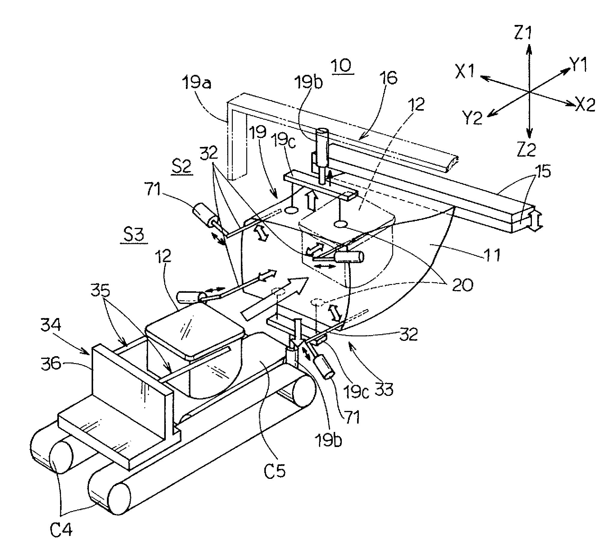
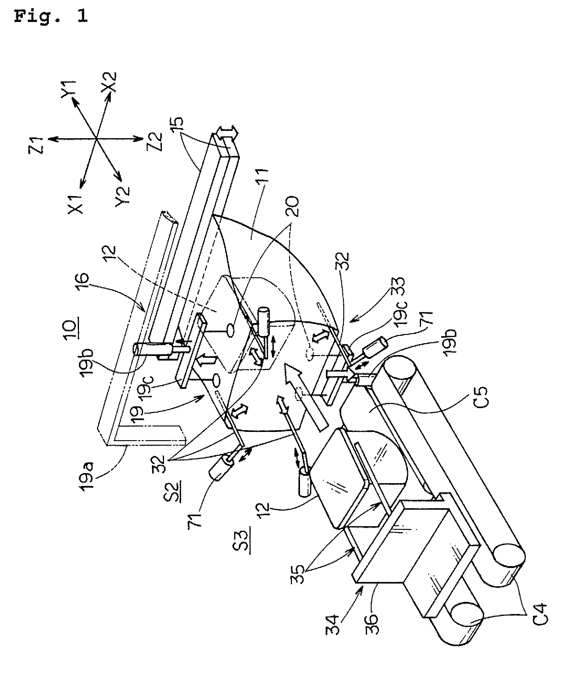
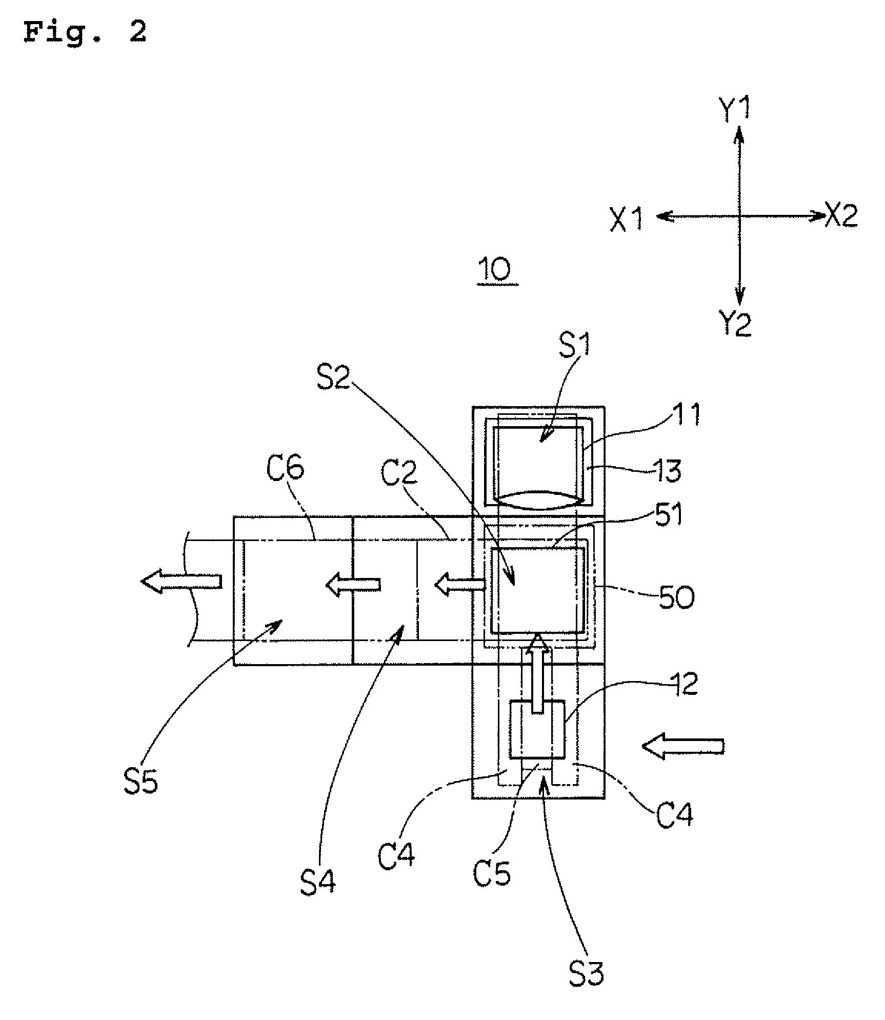
[0065]The present invention will now be described with reference to the attached drawings. It is to be noticed herein for clarity of the description that: Y1 direction designates a direction along which a container is inserted into a packaging bag; Y2 direction designates a direction opposite to the direction along which a container is inserted into a packaging bag, X1 direction designates one direction orthogonal to the Y1-Y2 direction in a plane; and X2 direction designates the other direction orthogonal to the Y1-Y2 direction in the plane.

[0066]It is to be noticed that a container used herein has employed a wafer case holding therein a plurality of wafer cassettes, or intermediate holders, in each of which a silicon wafer is housed. The wafer case is to be firstly inserted and packed in a packaging bag (an inner bag) and then placed in an outer bag made of aluminum for double packing. It is to be understood that the packing procedure by the outer bag is the same as that provided ...


PUM

PropertyMeasurementUnit
sizeaaaaaaaaaa
shapeaaaaaaaaaa
lengthaaaaaaaaaa

Abstract

A wafer case is inserted into a packaging bag, and an ear folding and shaping bar is pressed against a root of each corresponding triangular ear portion, making a folding back line in each triangular ear portion. Each of the triangular ear portions is folded back over a container side surface by a bag rear end ear folder. The folding operation for each of the triangular ear portions is performed precisely and smoothly.

Description

BACKGROUND OF THE INVENTION[0001]1. Field of the Invention[0002]The present invention relates to a container packaging apparatus, and in particular to a container packaging apparatus for packaging a container, for example, a wafer case containing a plurality of semiconductor wafers therein, so as to be packed in a packaging bag, such as a plastic bag.[0003]2. Description of the Related Art[0004]In order to prevent any damage or contamination during being transported, semiconductor wafers, such as silicon wafers, which have been manufactured in a wafer manufacturing plant are, in a typical practice of packing, loaded into a wafer cassette, an intermediate holder, made of synthetic resin, which is in turn packed in a wafer case whose cover can be closed tightly via a gasket (a packing member). The wafer case is further packed firstly in an inner bag made of nylon (the trade name of polyamide fiber) and then in an outer bag made of aluminum, in which the wafer case may be enclosed in r...

Claims


Application Information

Patent Timeline
Patent Type & Authority Patents(United States)
IPC IPC(8): B65B43/26B65B9/00B65B47/00
CPCB65B5/045B65B49/08B65B43/34B65B31/06
Inventor IMAO, SHUNICHI
Owner SUMCO CORP
Why Eureka
Try Eureka