Joining system head, joining system, and method of feeding and joining elements

a technology of joining system and head, which is applied in the direction of mechanical equipment, manufacturing tools, couplings, etc., can solve the problems of affecting the accuracy of the linear motion of the robot arm, the danger of damage to the bolt and/or the tongs, and the inability of the robot arm alone to achieve such a precise linear motion in an arbitrary direction of space, so as to improve the degree of automation

Inactive Publication Date: 2007-11-06
NEWFREY
View PDF31 Cites 7 Cited by
  • Summary
  • Abstract
  • Description
  • Claims
  • Application Information

AI Technical Summary

Benefits of technology

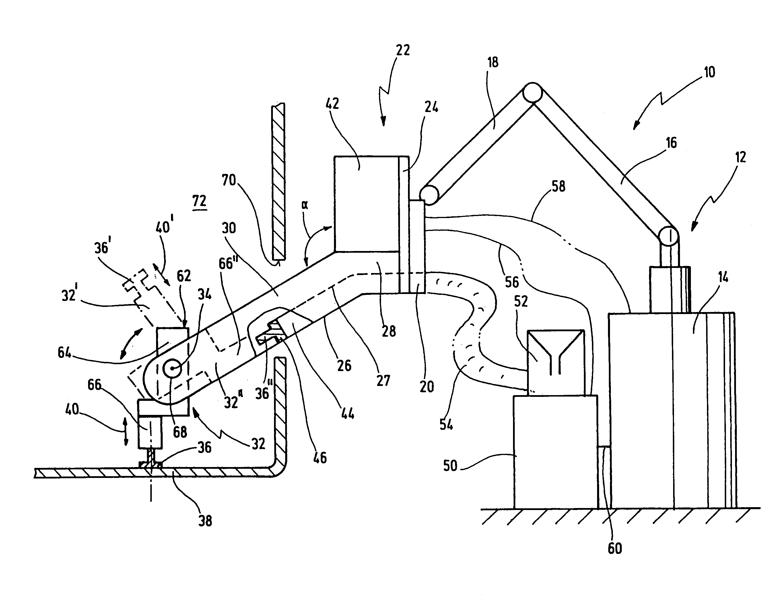
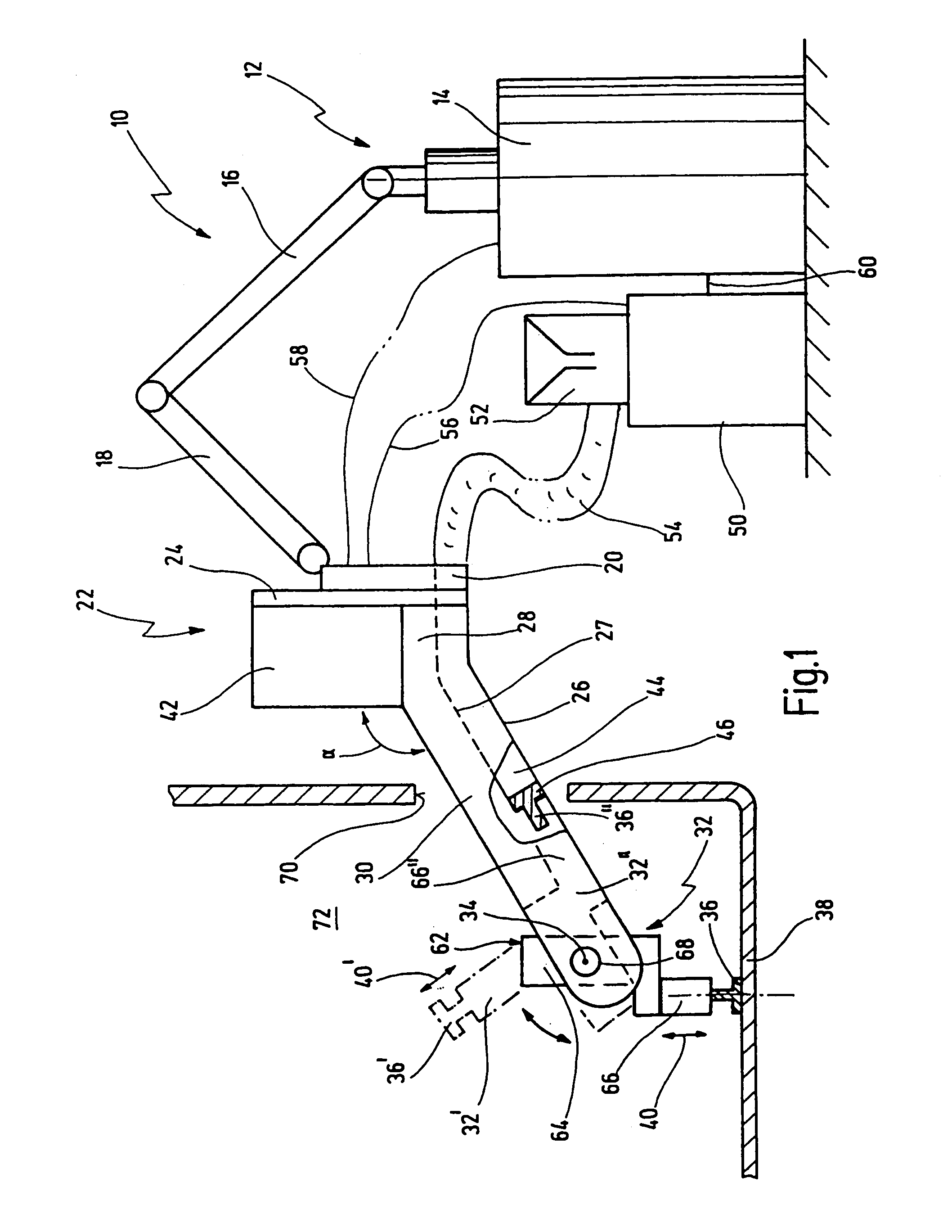
[0016]The joining system head according to the invention represents a completely novel concept. This is based on two fundamental ideas. One of these ideas consists in providing the control means at the joining system head, but spatially distanced from the holding means and the joining drive means. The holding means and the joining drive means can consequently form a joining tool of small dimensions and not much interference edge relevance. The other idea consists in feeding the elements by means of the feeding means, not immediately all the way to the holding means, but as far as a transfer station likewise distanced from the joining tool. In addition, means are provided to pass on each of the elements fed to the transfer station to the holding means from in front. In this way it is possible to keep the over-all axial length of the joining tool small, since no loading pin is required to position the elements through the holding means from behind.
[0036]Further, it is generally of advantage if the feeding means comprises a magazine for elements. In this way, it is possible always to place an element in readiness to be ‘grasped’ at the transfer station.

Problems solved by technology

Otherwise, owing to the one-piece tongs, there would be danger of damage to the bolt and / or the tongs.
The robot arm alone is not capable of such a precise linear motion in an arbitrary direction of space.

Method used


Image

  • Joining system head, joining system, and method of feeding and joining elements
  • Joining system head, joining system, and method of feeding and joining elements
  • Joining system head, joining system, and method of feeding and joining elements

Examples


first embodiment

[0091]FIG. 8 shows a transfer station 46 of the feeding means 44. At the transfer station 46, two opposed sensors 136 (for example a light barrier) are provided, detecting whether there is a bolt 36 in the transfer station 46 or not.

[0092]The feeding means 44 consists essentially of a tube or hose 138, bent off inward in the region of the transfer station 46. The bolts 36 are fed shank first from the individualizing device 52 through the feeding means 44. Consequently the head of the bolt 36 will strike the rolled edge of the tube 138 and remain so in the transfer station 46. Thus the shank of the bolt 36 protrudes from the tube 138.

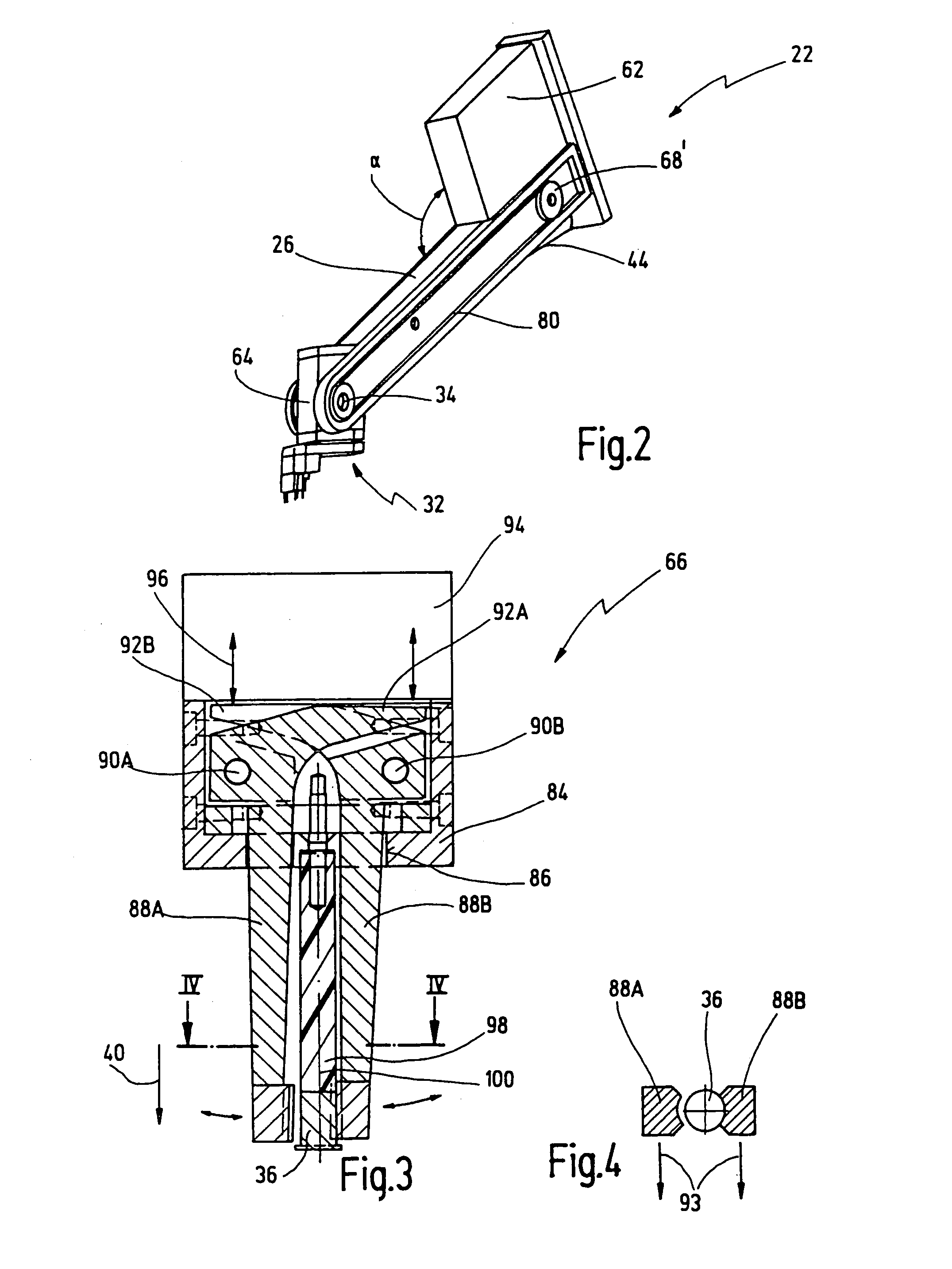
[0093]The holding means 66 can now be run with opened jaws 88A, 88B all the way to the bolt 36 and grasp it. Then the holding means 66 is swung back again, out of the plane of the paper in the representation of FIG. 8. It will be understood that at the transfer station 46, a suitable lateral recess must be provided in the tube 138, though not explicitly ...

third embodiment

[0096]a transfer station 46″ is shown in FIGS. 10 and 11. In this embodiment, the bolts 36 are conveyed by way of a tube 138″ into a bolt receptacle 154 of a swingable rotational segment 152. The segment 152 is rotatable about an axis 153 oriented transverse to the axis of the tube 138″ and transverse to the orientation of the bolt 36 in the transfer position.

[0097]In FIGS. 10 and 11, the segment 152 is in a transfer position. In this position, a pneumatic cylinder 156 serves to push the bolt 36 by means of a plunger 158 between two tension jaws 160, between which the bolt 36 is then hold in a defined manner. Then the segment 152 is turned back to pick up another bolt 36 in the receiving position shown dotted, flush with the tube 138″. This embodiment has the advantage that the bolts 36 can be conveyed at high speed through the tube 138″. Hence short cycle periods can be achieved.

[0098]Another embodiment of a welding head according to the invention is generally designated 170 in FIG...


PUM

PropertyMeasurementUnit
angleaaaaaaaaaa
angleaaaaaaaaaa
angleaaaaaaaaaa

Abstract

A joining system head (22) is proposed for fixation to a movable frame (12), in particular to a robot (12), havinga holding means (66) for an element (36) to be joined to a part (38),a joining drive means (64) to move the holding means (66) along a joining direction (40) for joining, anda feeding means (44) for feeding elements (36) to the joining system head (22).Here a control means (42) to control the joining drive means (64) is arranged at the joining system head (22) spatially distanced from the holding means (66) and the joining drive means (64), so that the holding means (66) and the joining drive means (64) form a joining tool (32) of small dimensions, and means (68) are provided to pass on the elements (36) fed to a transfer station (46) of the feeding means (44) in each instance to the holding means (66) from in front.

Description

BACKGROUND AND SUMMARY OF THE INVENTION[0001]The present invention relates to a joining system head for attachment to a movable frame, in particular to a robot, having[0002]A holding means for an element to be joined to a part, and[0003]A joining drive means to move the holding means along a joining direction for joining.[0004]A feeding means for feeding elements to the joining system head.[0005]The present invention relates further to a joining system having a robot movable on at least two coordinate axes and a joining system head attached to the robot. Lastly, the present invention relates to a method of feeding elements from a stationary unit to a movable joining system head and joining said elements to parts by means of the joining system head.[0006]Such a joining system head, such a joining system and such a method of feeding and joining elements by means of a joining system head are generally known. The term ‘joining’ in the present context is intended to refer to all ways of ...

Claims


Application Information

Patent Timeline
Patent Type & Authority Patents(United States)
IPC IPC(8): B23K11/04B23K9/20
CPCB23K9/206Y10T403/70
Inventor MULLER, MANFREDOBERMANN, WOLFGANGKRENGEL, MICHAELSCHMITT, KLAUS GISBERT
Owner NEWFREY
Why Eureka
Try Eureka