Method and apparatus for transforming moving picture coding system

Inactive Publication Date: 2007-11-06
SOVEREIGN PEAK VENTURES LLC
View PDF16 Cites 3 Cited by
  • Summary
  • Abstract
  • Description
  • Claims
  • Application Information

AI Technical Summary

Benefits of technology

[0036]In view of the forgoing, an object of the present invention is to provide a method and apparatus for perfor

Problems solved by technology

Therefore, it is not realistic to handle such a massive code amount in digital format without using any transformation.
A plurality of moving picture coding standards are thus to be used, resulting in the problem to be solved that coded data (hereinafter referred to as bit-stream) in such standards is not compatible with each other.
For example, although a decoder based on MPEG-4 is specified to be capab

Method used


Image

  • Method and apparatus for transforming moving picture coding system
  • Method and apparatus for transforming moving picture coding system
  • Method and apparatus for transforming moving picture coding system

Examples


Example

[0125]In the first embodiment, the transformation based on flowcharts illustrated in FIGS. 9 to 11 is performed. Among process steps enclosed with bold lines in FIG. 9, the intra-inter coding mode control (S1) is performed according to the flowchart illustrated in FIG. 10, and change of coding data on a macroblock-by-macroblock basis for the rate control (S2) is performed according to the flowchart illustrated in FIG. 11.

[0126]Herein, it is assumed that, as conditions for the rate control, a coding rate of H.261 is 64 kbps, a coding rate of MPEG-4 is also 64 kbps, and that a buffer size of the output buffer is 6.4 kbit.

[0127]In the intra-inter coding mode control illustrated in FIG. 10, when the H.261 data sequence is transformed to the MPEG-4 data sequence, the predetermined number (3 in this embodiment) of macro blocks are selected from macro blocks belonging a moving region in descending order of refreshing period, and the coding mode of the selected macro blocks are forcedly cha...

Example

[0148]The second embodiment is next described.

[0149]The second embodiment describes the transformation method from MPEG-4 to H.261. The transformation operations in this embodiment are performed based on flowcharts illustrated in FIGS. 9, 12 and 13.

[0150]Among processing steps enclosed with bold lines, the intra-inter coding mode control is performed according to the flowchart in FIG. 12, and the change of coding data on a macroblock-by-macroblock for the rate control is performed according to the flowchart in FIG. 13.

[0151]The difference of this embodiment from the first embodiment is mainly explained to simplify the explanation.

[0152]Herein, it is assumed that macro blocks more than needed are intra-coded to improve the error resistance although the coding efficiency of MPEG-4 is higher than that of H.261.

[0153]In the control for the intra-inter coding mode illustrated in FIG. 12, coding modes of intra-coded macro blocks are set at ‘U’ (unfixed) except macro block with the maximum...

Example

[0164]A fourth embodiment is next explained with FIG. 16.

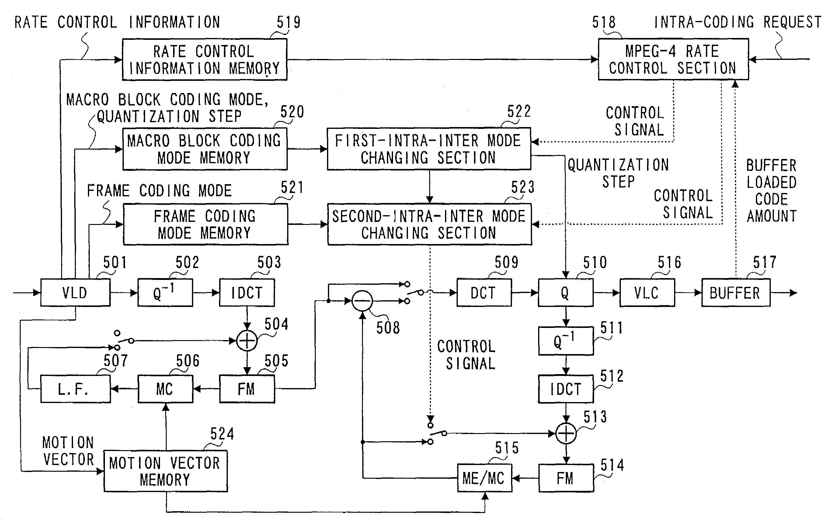
[0165]An apparatus of the fourth embodiment performs the transformation from MPEG-4 to H.261, inversely to the apparatus of the third embodiment. In FIG. 16, 601 is a variable length decoding section, 602 is an inverse quantization section, 603 is an inverse DCT section, 604 is an adder, 605 is a frame memory, and 606 is a motion compensation section, thus composing a MPEG-4 decoder.

[0166]A decoded image is provided to an H.261 coder through frame memory 605.

[0167]607 is a subtracter, 608 is a DCT section, 609 is a quantization section, 610 is an inverse quantization section, 611 is an inverse quantization section, 612 is an adder, 613 is a frame memory, 614 is a motion prediction and motion compensation section, 615 is a loop filter, 616 is a variable length coding section, and 617 is an output buffer, thus composing the H.261 coder. 618 is an H.261 rate control section, and achieves the control described in FIGS. 9, 12 and 1...


PUM


Abstract

A first data sequence generated by a first moving picture coding system having an intra-frame coding mode and an inter-frame coding mode is transformed to a second data sequence generated by a second moving picture coding system having an intra-frame coding mode and an inter-frame coding mode. The method includes prereading a coding mode of a successive frame succeeding a present frame from the first data sequence, judging whether or not a preread coding mode of the successive frame is the intra-frame coding mode and determining whether or not to code the present frame by the second moving picture coding system corresponding to a generated code amount of the second data sequence when the coding mode of the successive frame is the intra-frame coding mode. Data coded by the intra-frame coding mode existing in the first data sequence is transformed to the second data sequence.

Description

CROSS-REFERENCE TO RELATED APPLICATIONS[0001]This is a divisional of U.S. application Ser. No. 09 / 511,488, filed Feb. 23, 2000 now U.S. Pat. No. 6,625,211, the entire disclosure of which is expressly incorporated by reference herein in its entirety.BACKGROUND OF THE INVENTION[0002]1. Field of the Invention[0003]The present invention relates to a method and apparatus for transforming a moving picture coded by a coding system into another moving picture coded by another coding system.[0004]2. Description of the Related Art[0005]With the progress of multimedia techniques for handling voice, image and other data collectively, conventional information media such as a newspaper, magazine, television, radio, and telephone, which are means for conveying information to people, become subjects for the multimedia.[0006]Generally, the multimedia are considered to show not only characters but also other information such as figures, voices, or particularly images, associated with characters at th...

Claims


Application Information

Patent Timeline
IPC IPC(8): H04N7/12H04B1/66H04N11/02H04N11/04H04N7/26H04N7/36H04N7/46H04N7/50
CPCH04N19/105H04N19/40H04N19/159H04N19/176H04N19/172H04N19/46H04N19/115H04N19/61H04N19/124H04N19/132H04N19/146H04N19/152H04N19/523H04N19/587H04N19/139
Inventor ETOH, MINORUUENOYAMA, TSUTOMUIWASAKI, OSAMUKOMIYA, DAISAKU
Owner SOVEREIGN PEAK VENTURES LLC
Why Eureka
Try Eureka