Multi-input optical switch

a multi-input, optical switch technology, applied in the direction of optics, optical elements, instruments, etc., can solve the problems of increased cost, complicated overall configuration, and long-term durability and detection reliability, and achieve excellent durability and detection reliability

Inactive Publication Date: 2007-11-06
STANLEY ELECTRIC CO LTD
View PDF3 Cites 68 Cited by
  • Summary
  • Abstract
  • Description
  • Claims
  • Application Information

AI Technical Summary

Benefits of technology

[0013]In accordance with an aspect of the presently disclosed subject matter, a multi-input optical switch which can detect absolute displacements at a high precision, and is excellent in durability and reliability, can be provided.
[0020]The multi-input optical switch according to the disclosed subject matter can be configured to detect the tilted direction, the rotational angle, and the downward movement by identifying the pulse modulation code of the pulsed light detected by the photo sensor when the operation lever is tilted, rotated, and depressed. As a result, the absolute displacements can be detected at a high precision, and the portions relating to the switch detection do not have mechanical contacts, resulting in a multi-input optical switch that is excellent in durability and detection reliability.

Problems solved by technology

The multi-input switch 50 configured as described above has mechanical contacts within the components, which causes problems in durability and detection reliability for a long-term operation.
In order to detect the tilted direction by a tilting operation applied to the operation lever 51, it is necessary to provide the potentiometers 56 with an external component and circuit which apply signal conversion, such as voltage conversion and A / D conversion, to an output therefrom, resulting in a complicated overall configuration, and an increased cost.
Similarly, if the operation lever 51 is rotated at a high speed, a detection miss may occur, resulting in a possible degradation of detection precision.

Method used


Image

  • Multi-input optical switch
  • Multi-input optical switch
  • Multi-input optical switch

Examples


Embodiment Construction

[0038]A description will now be given of exemplary embodiments of the disclosed subject matter with reference to FIGS. 1 to 16. Similar or identical components are denoted by the same numerals throughout the drawings. The described embodiments are only examples of the disclosed subject matter, and thus include certain technical features. The following description should not be deemed and is not intended to limit the scope of the disclosed subject matter to the depicted embodiments.

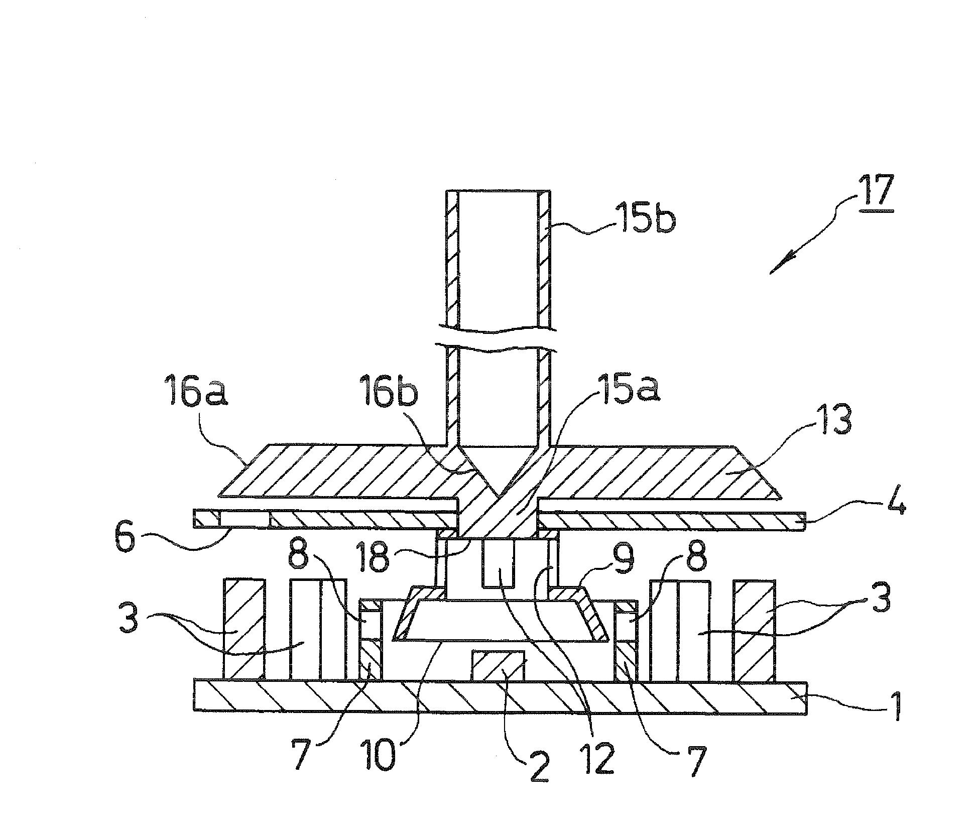
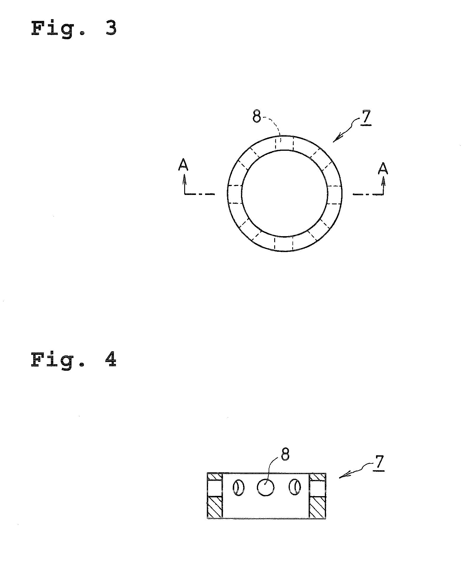
[0039]A base plate 1 carrying LEDs 3 and a photo sensor 2 can include a first mask 7, a second mask 4, a third mask 9, and a light guiding body 13.

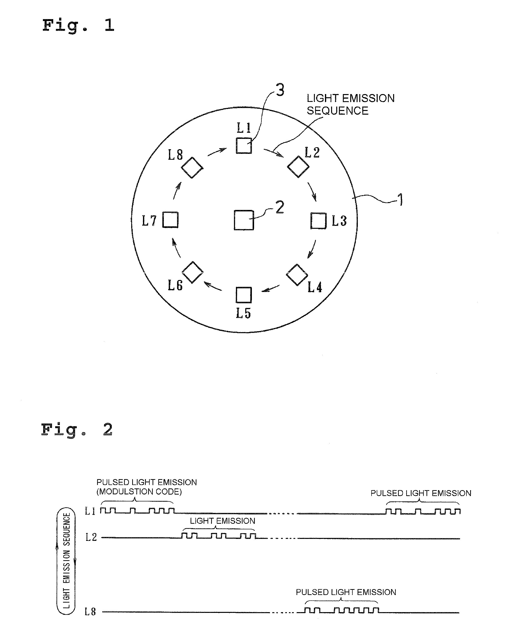
[0040]On the approximately circular base plate 1, at least one photo sensor 2 can be mounted at the substantial center thereof. Multiple LEDs 3 are arranged at positions separated by approximately the same angular interval on approximately the same circle about the photo sensor 2, as shown in FIG. 1. According to this embodiment, eight LEDs are used.

[0041]The ph...


PUM


Abstract

A multi-input optical switch can include a base plate that carries at least one photo sensor and multiple LEDs which are arranged at positions separated by approximately the same angular interval. A first mask can be formed in an approximately cylindrical shape and can include multiple through holes. A second mask can be formed as an approximately flat light blocking plate, and can include a translucent area. A translucent light guiding body can include an approximately flat plate portion, a protruded portion which extends downward from a center portion of the plate portion, a rod portion which extends upward from the center portion of the plate portion, a first total reflection surface and a second total reflection surface. A third mask can be provided with a tubular cup shape that diverges downward, and has an opening at a bottom end, a step portion at an intermediate position thereof, and at least one through hole on an upper cylindrical wall above the step portion. A rod portion of the light guiding body can be operated to freely tilt, rotate, and move up and down.

Description

[0001]This application claims the priority benefit under 35 U.S.C. § 119 of Japanese Patent Application No. 2005-346265 filed on Nov. 30, 2005, which is hereby incorporated in its entirety by reference.BACKGROUND[0002]1. Field[0003]The presently disclosed subject matter relates to a multi-input optical switch. More particularly, the presently disclosed subject matter relates to a multi-input optical switch that can include an optical system which detects a tilted direction, a rotational angle, and up / down of an operation lever by means of light as a detection medium.[0004]2. Description of the Related Art[0005]There has conventionally been proposed a multi-input switch as shown in FIG. 17, which has multiple operation means. In FIG. 17, the multi-input switch 50 includes an operation lever 51, a first switch unit 52 which detects whether the operation lever 51 is depressed or not (by a depressing operation applied to the operation lever 51), a second switch unit 53 which detects a t...

Claims


Application Information

Patent Timeline
Patent Type & Authority Patents(United States)
IPC IPC(8): G02B6/00G02B6/26
CPCG01C9/00G02B6/42G02B6/3604G02B6/425G02B6/4214
Inventor ISHIYAMA, YUTAKAURABE, HIDEKI
Owner STANLEY ELECTRIC CO LTD
Why Eureka
Try Eureka