Hollow laminated piezoelectric element and its manufacturing method

a piezoelectric element and laminate technology, applied in the direction of machines/engines, generators/motors, mechanical equipment, etc., can solve the problems of insufficient reliability, difficult insulate the internal peripheral surface of the ceramic laminate, peeling of the insulator, etc., to achieve sufficient durability, suppress cracks in the piezoelectric layer, and improve durability

Inactive Publication Date: 2006-06-08
DENSO CORP
View PDF5 Cites 5 Cited by
  • Summary
  • Abstract
  • Description
  • Claims
  • Application Information

AI Technical Summary

Benefits of technology

[0014] The present invention has been made in the light of the above conventional problems, and provides a hollow laminated piezoelectric element having excellent durability and reliability and the capable of obtaining a high output, and a method of manufacturing the hollow laminated piezoelectric element.

Problems solved by technology

Therefore, it is difficult to insulate the internal peripheral surface of the ceramic laminate, and sufficient reliability cannot be obtained.
However, according to the above insulation method, the adhesive strength of the insulator is not sufficient, and stress generated by piezoelectric displacement is repetitively applied, thereby causing peeling-off of the insulator.
Consequently, moisture enters the internal peripheral surface, and causes an insulation failure.
Therefore, there are many non-insulation parts, and it becomes difficult to insulate these parts.
However, in the case of the partial electrode structure type, stress generated due to piezoelectric displacement is concentrated at the ends of the internal electrode layers, and this has a risk of the occurrence of cracks.
This inconvenience becomes extreme when a high output is produced.
Therefore, it is difficult to obtain sufficient durability and reliability of the piezoelectric actuator for a long-term use as well as to obtain a high output.
As explained above, according to the conventional hollow laminated piezoelectric element, it is not easy to secure insulation, obtain sufficient durability and reliability, and obtain a high output.

Method used


Image

  • Hollow laminated piezoelectric element and its manufacturing method
  • Hollow laminated piezoelectric element and its manufacturing method
  • Hollow laminated piezoelectric element and its manufacturing method

Examples


first embodiment

[0061] In the first embodiment, the inside peripheral slits preferably have a ring shape extending in the whole peripheral directions.

[0062] In this case, the inside peripheral slits can sufficiently relax stress generated due to piezoelectric displacement and can further suppress the occurrence of cracks.

[0063] Preferably, the ceramic laminate has an internally terminated structure in the outside periphery having at least a portion of outside peripheral ends of the internal electrode layers terminated within the ceramic laminate so that at least a portion of the outside peripheral ends of the internal electrode layers is not exposed to the outside peripheral surface of the ceramic laminate, and the outside peripheral surface of the ceramic laminate has outside peripheral slits having trenches provided in the peripheral direction toward the inside of the piezoelectric layers from the outside peripheral surface.

[0064] In this case, because the ceramic laminate has an internally ter...

second embodiment

[0077] In the second embodiment, at the adhesive layer forming step, an adhesive layer is formed on the electrode material and the spacer layer, and on the vanishing slit layer and the spacer layer, and at the punching step, the green sheet is punched to obtain an electrode material-containing piece comprising the sequentially laminated green sheet, electrode material, spacer layer, and adhesive layer and having a through hole in the center, and a vanishing slit layer-containing piece comprising the sequentially laminated green sheet, vanishing slit layer, spacer layer, and adhesive layer and having a through hole in the center.

[0078] In this case, the adhesive layer is formed on both the electrode material-containing piece and the vanishing slit layer-containing piece obtained at the punching step. Therefore, both can be laminated easily at the subsequent laminating step.

[0079] A material that can secure electric insulation is used for the spacer layer and the adhesive layer in th...

example 1

[0081] Example 1

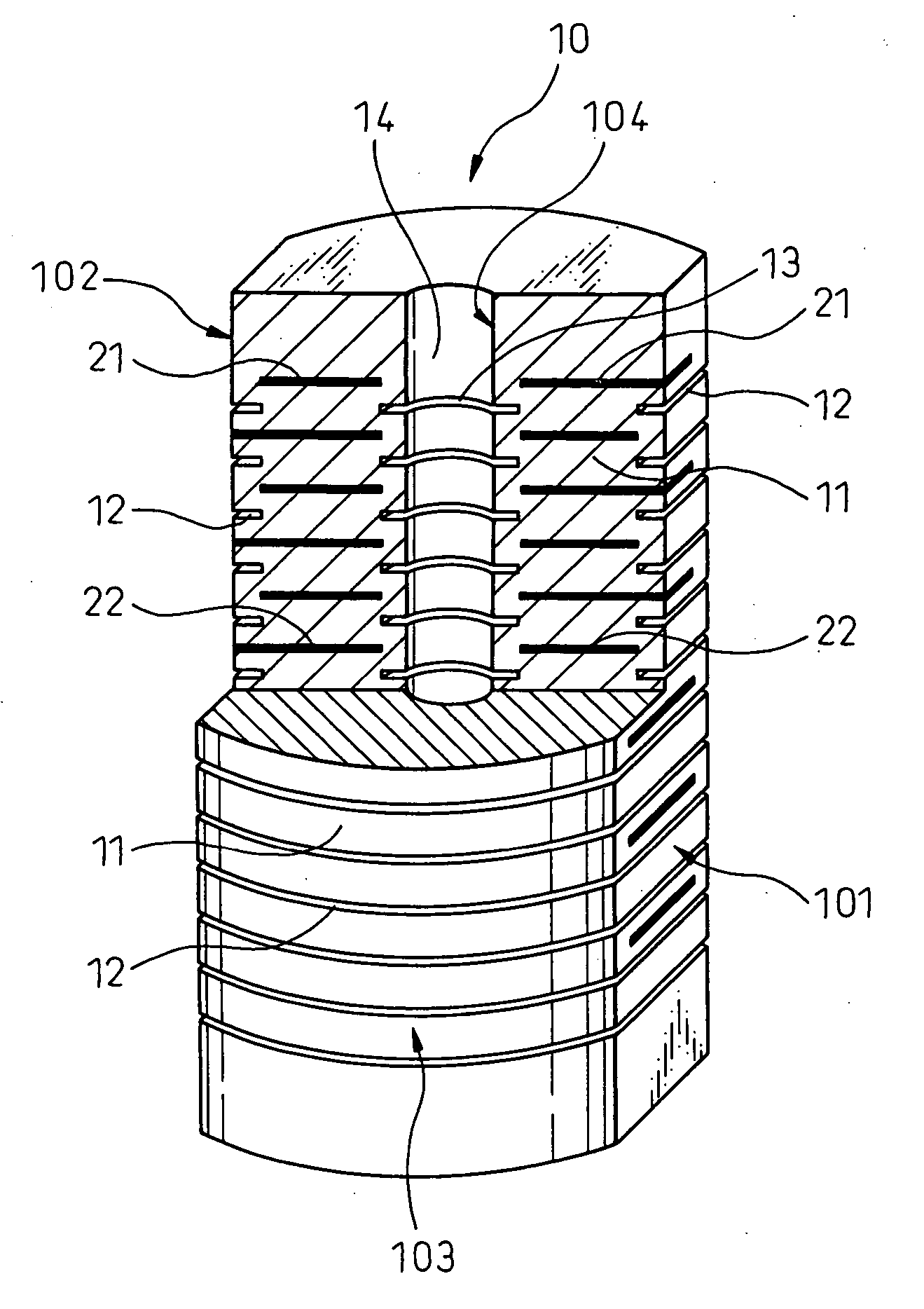
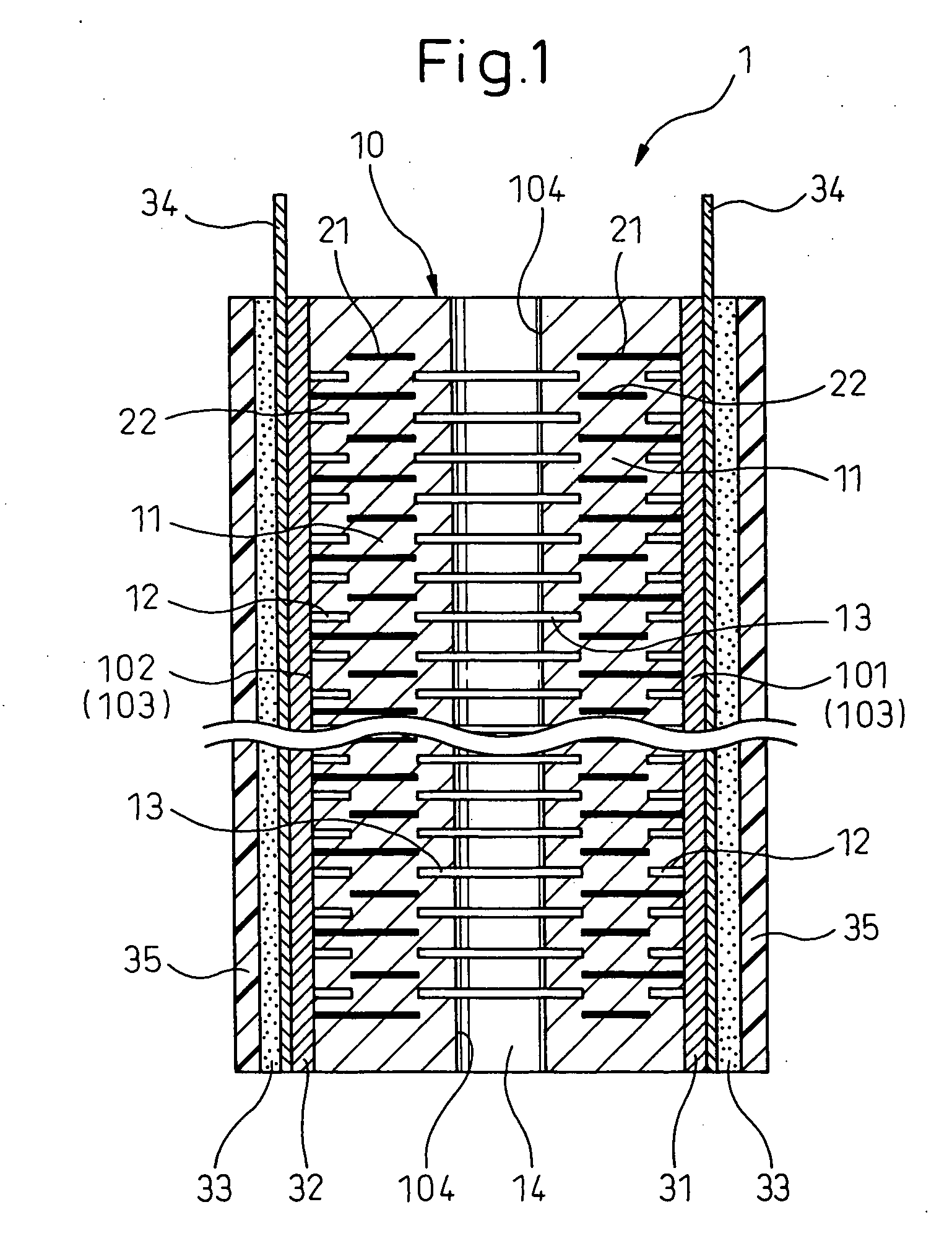
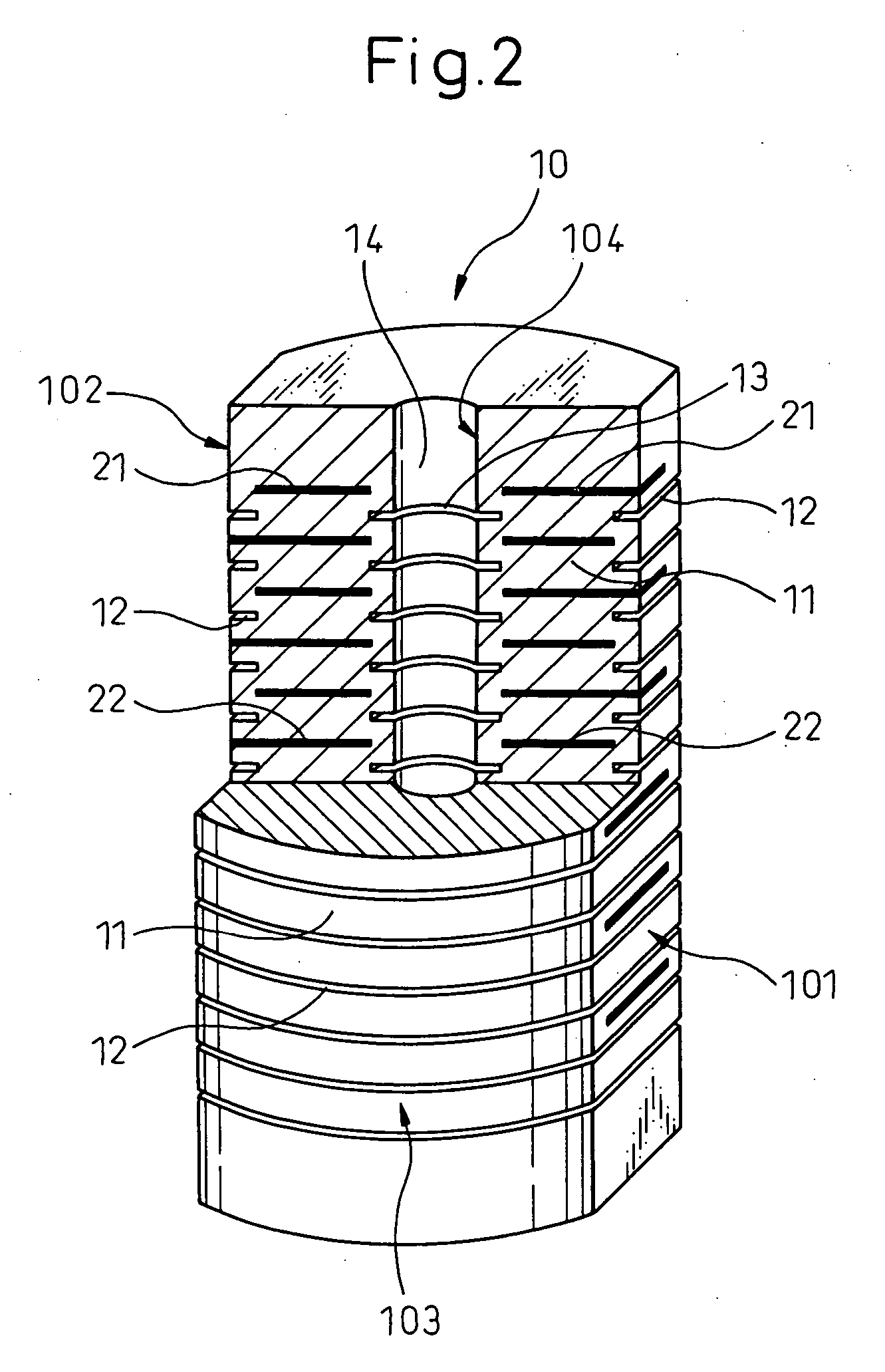
[0082] A hollow laminated piezoelectric element and a method of manufacturing the hollow laminated piezoelectric element according to embodiments of the present invention are explained with reference to FIG. 1 to FIG. 11.

[0083] As shown in FIG. 1, a hollow laminated piezoelectric element 1 according to the present embodiment comprises a ceramic laminate 10 that is formed by having alternately laminated piezoelectric layers 11 made of a piezoelectric material and internal electrode layers 21 and 22 having conductivity and by having a center through hole 14 provided to pass through the ceramic laminate 10 along a lamination direction.

[0084] The ceramic laminate 10 has an internally terminated structure in the inside periphery having at least a portion of inside peripheral ends of the internal electrode layers 21 and 22 terminated within the ceramic laminate 10 so that at least a portion of the inside peripheral ends of the internal electrode layers 21 and 22 is not e...


PUM

PropertyMeasurementUnit
thicknessaaaaaaaaaa
thicknessaaaaaaaaaa
thicknessaaaaaaaaaa

Abstract

A hollow laminated piezoelectric element having excellent durability and reliability and capable of obtaining a high output, and a method of manufacturing the hollow laminated piezoelectric element are provided. A hollow laminated piezoelectric element 1 comprises a ceramic laminate 10 that is formed by having alternately laminated piezoelectric layers 11 made of a piezoelectric material and internal electrode layers 21 and 22 having conductivity and by having a center through hole 14 formed to pass through the ceramic laminate 10 along a lamination direction. The ceramic laminate 10 has an internally terminated structure in the inside periphery having at least a portion of inside peripheral ends of the internal electrode layers 21 and 22 terminated within the ceramic laminate 10 so that at least a portion of the inside peripheral ends of the internal electrode layers 21 and 22 is not exposed to the inside peripheral surface 104 of the ceramic laminate 10. The inside peripheral surface 104 of the ceramic laminate 10 has inside peripheral slits 13 having trenches provided in the peripheral direction toward the inside of the piezoelectric layers 11 from the inside peripheral surface 104.

Description

[0001] This application is a new U.S. patent application that claims benefit of JP 2004-353164, filed Dec. 6, 2004, the entire contents of each of which are hereby incorporated by reference.FIELD OF THE INVENTION [0002] The present invention relates to a hollow laminated piezoelectric element that is applied to a piezoelectric actuator or the like, and a method of manufacturing the hollow laminated piezoelectric element. BACKGROUND OF THE INVENTION [0003] In recent years, from the viewpoint of environmental concerns, fuel consumption, and the exhaust gas of automobiles, development of fuel injectors for automobiles using a laminated piezoelectric element is progressing. [0004] The laminated piezoelectric element usually contains a ceramic laminate that is formed by having alternately laminated piezoelectric layers made of a piezoelectric material and internal electrode layers having conductivity. A voltage is applied to between internal electrodes, thereby generating a displacement ...

Claims


Application Information

Patent Timeline
Patent Type & Authority Applications(United States)
IPC IPC(8): H01L41/083F02M51/06H01L41/187H01L41/22H01L41/273H01L41/297H01L41/339
CPCF02M51/0603F02M61/168F02M2200/80F02M2200/9007F02M2200/9038F02M2200/9046F02M2200/9053H01L41/0835H01L41/0838H01L41/273H01L41/339H10N30/505H10N30/508H10N30/053H10N30/089
Inventor IWASE, AKIOKADOTANI, SHIGEITOU, TETSUJI
Owner DENSO CORP
Why Eureka
Try Eureka