
System and method for controlling speed of an engine

a technology of engine speed and control system, which is applied in the direction of electrical control, hybrid vehicles, instruments, etc., can solve the problems of undesired nvh level, achieve the effect of reducing noise and vibration, and reducing battery charging ra

Active Publication Date: 2007-11-06
FORD GLOBAL TECH LLC
View PDF12 Cites 41 Cited by
  • Summary
  • Abstract
  • Description
  • Claims
  • Application Information

AI Technical Summary

Benefits of technology

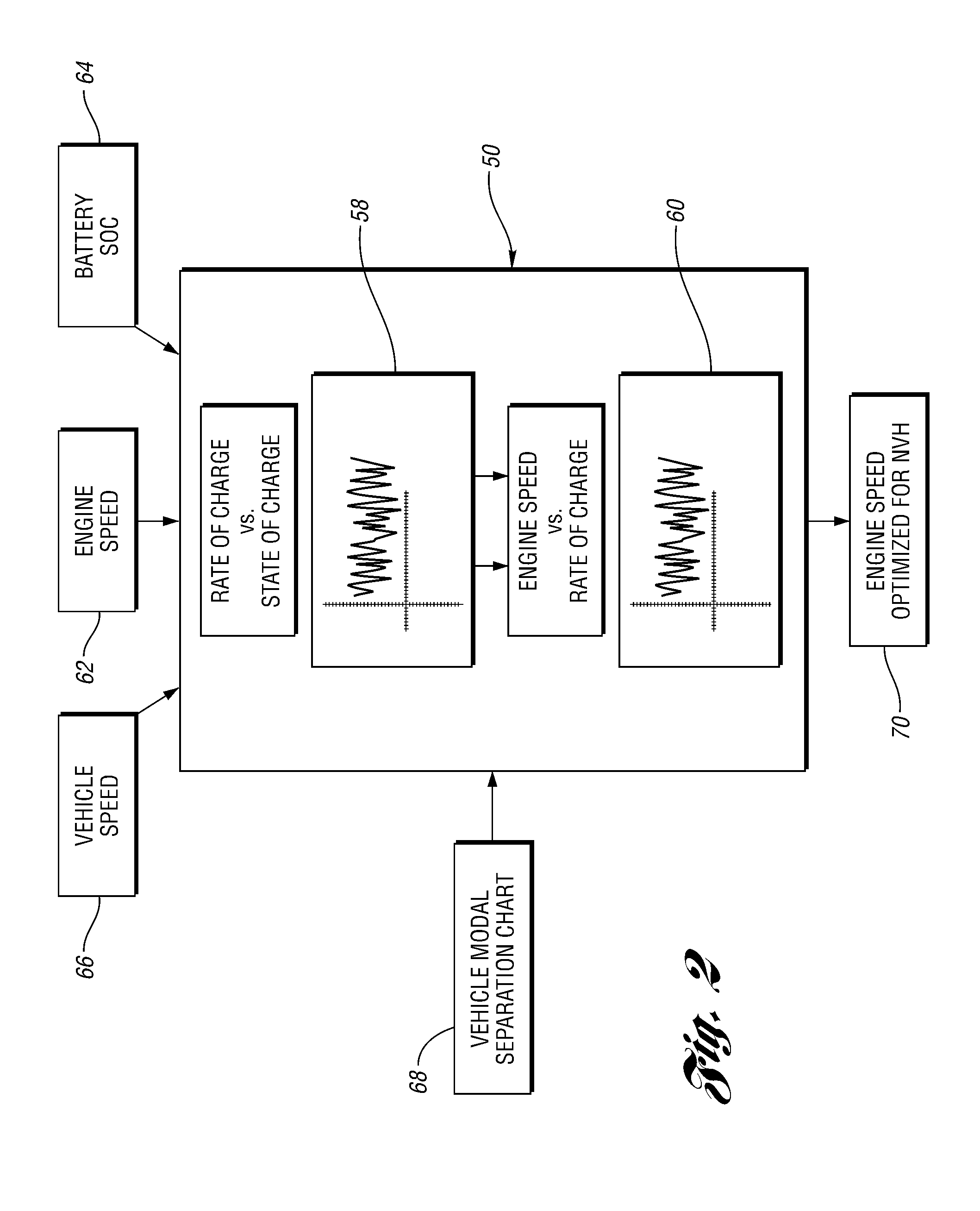
[0012]The example given above provides a mechanism for adjusting the desired engine speed so that it lies within one of the predetermined engine speed ranges as indicated by the Modal Separation Chart; however, it may also be advantageous to adjust the engine speed based on the noise-vibration level. For example, even if the desired engine speed is within one of the predetermined engine speed ranges, the determined noise-vibration level may not be within the target range. In such a case, the engine speed is again adjusted, it is again analyzed to see if fits within one of the predetermined engine speed ranges, and a new noise-vibration level for the vehicle is determined. The new noise-vibration level is examined to see if it is within the target range. Thus, embodiments of the present invention provide for adjusting the engine speed based on a number of factors, thereby providing additional comfort for the vehicle occupants.
[0013]Although embodiments of the present invention may be directed toward controlling the speed of the engine when the engine is idling, at least some embodiments can be used for higher engine speeds. For example, when the vehicle is moving at a relatively low speed, it may still be advantageous to use the present invention to help ensure that noise and vibration levels within the passenger compartment are acceptable. Once the vehicle speed increases beyond a certain point, vibrations from the road and wind noise can mask much of the noise and vibration within the vehicle passenger compartment. Embodiments of the present invention can also take advantage of this relationship. For example, the NVH level for the vehicle can be examined for a number of battery charging rates and engine idle speeds. Using knowledge of the vehicle speed, it may be possible to choose higher battery charging rates while still maintaining an acceptable NVH level. This is possible, because embodiments of the present invention consider the change in noise and vibration for various mechanical systems as the engine speed changes. Thus, choosing the appropriate engine speed during a high rate of battery charging can still provide a lower NVH level than when the battery charging rate is low.

Problems solved by technology

Even though the desired engine speed was filtered through the modal separation chart, and therefore, should not be at or near the resonant frequency of any of the vehicle mechanical systems included on the chart, the NVH level may still be undesirably high, particularly if the high voltage battery is being charged.

Method used


Image

  • System and method for controlling speed of an engine
  • System and method for controlling speed of an engine
  • System and method for controlling speed of an engine

Examples


Embodiment Construction

)

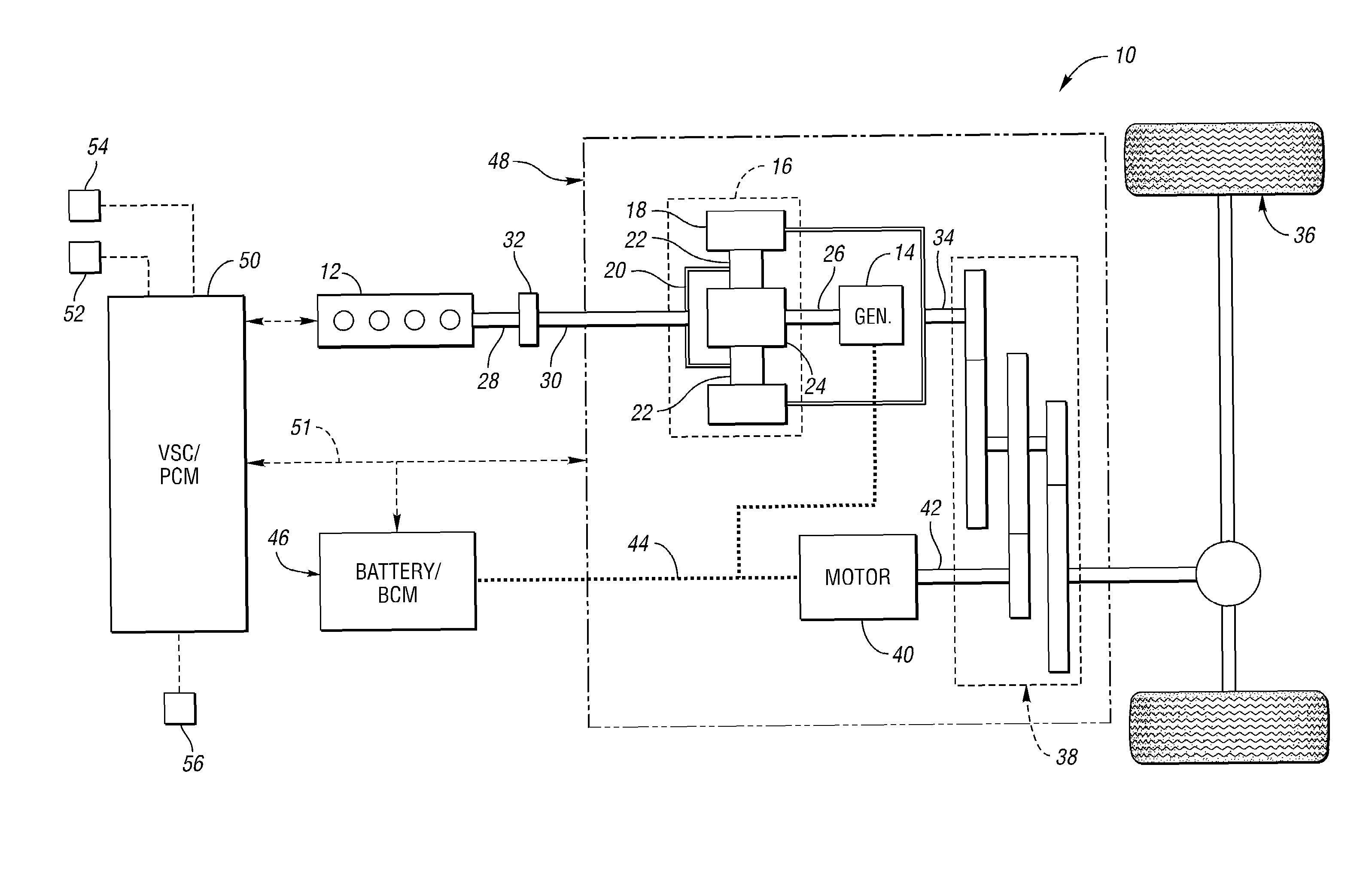
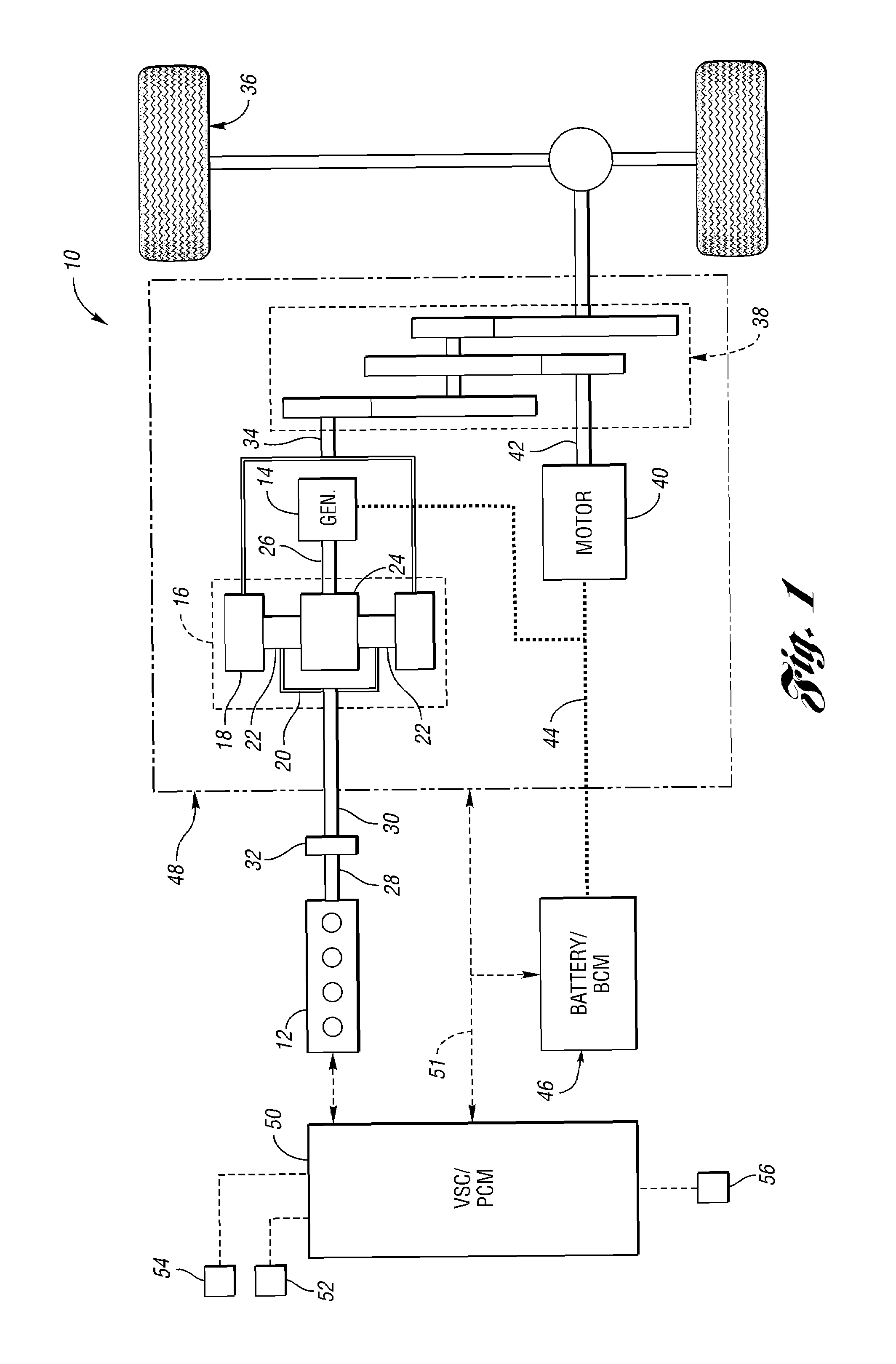
[0023]FIG. 1 shows a schematic representation of a vehicle 10 in which the system and method of the present invention can be used. The vehicle 10 includes an engine 12 and an electric machine, or generator 14. The engine 12 and the generator 14 are connected through a power transfer arrangement, which in this embodiment, is a planetary gear arrangement 16. Of course, other types of power transfer arrangements, including other gear sets and transmissions, may be used to connect the engine 12 to the generator 14. The planetary gear arrangement 16 includes a ring gear 18, a carrier 20, planet gears 22, and a sun gear 24.

[0024]The generator 14 can also be used as a motor, outputting torque to a shaft 26 connected to the sun gear 24. Similarly, the engine 12 outputs torque to a crankshaft 28, which is connected to a shaft 30 through a passive clutch 32. The clutch 32 provides protection against over-torque conditions. The shaft 30 is connected to the carrier 20 of the planetary gear arr...


PUM


Abstract

A system and method for controlling the speed of an engine includes determining a desired engine power output and engine speed, and determining whether the desired engine speed is within one of a number of predetermined engine speed ranges. It is then determined whether a noise-vibration level for the vehicle is within a target range when it is determined that the desired engine speed is within one of the predetermined engine speed ranges. The noise-vibration level is a function of at least one of a corresponding vibration level for one or more vehicle mechanical systems, and a noise level for the passenger compartment for the engine operating at the desired engine speed. The engine is then controlled at the desired engine speed when the determined noise-vibration level is within a target range, and it is determined that the desired engine speed is within one of the predetermined engine speed ranges.

Description

BACKGROUND OF THE INVENTION[0001]1. Field of the Invention[0002]The present invention relates to a system and method for controlling the speed of an engine in a vehicle.[0003]2. Background Art[0004]The operation of an engine in a vehicle can, at times, create undesirable noise and vibrations that detract from vehicle passenger comfort. This may be particularly true if the engine is allowed to operate at a frequency that is at or near the resonant frequency of a mechanical component or system within the vehicle. When this occurs, the vibrations in the mechanical system caused by the engine can increase significantly. To address this problem, at least one known vehicle predetermines allowable engine idle speeds such that the frequency of engine operation at these speeds will not match the resonant frequency of any of a chosen number of vehicle mechanical components and systems. In such a case, the allowable engine idle speed is a static value that is not adjusted in light of changing ...

Claims


Application Information

Patent Timeline
Patent Type & Authority Patents(United States)
IPC IPC(8): F02D41/14G06G7/70
CPCB60K6/445B60W10/06F02D41/1498F02D31/001B60W20/00B60W2710/0644Y02T10/6239F02D41/1406F02D2200/025F02N11/0818Y02T10/62B60W10/08B60W20/15
Inventor LEDGER, DAVIDDOLAN, GEORGEKONOPA, JASONBOISMIER, JEFFREYCADWELL, FLOYD
Owner FORD GLOBAL TECH LLC
Learn More