Transmission

a technology of transmission and transmission shaft, applied in the field of transmission, can solve the problems of large size, heavy weight, and inability to achieve smooth drivability during a gear change operation, and achieve the effect of more smooth drivability

Inactive Publication Date: 2007-11-13
HONDA MOTOR CO LTD
View PDF13 Cites 6 Cited by
  • Summary
  • Abstract
  • Description
  • Claims
  • Application Information

AI Technical Summary

Benefits of technology

[0009]Thus, a driving force from the engine can be continuously transmitted to the axle shaft even when a gear change operation is being performed. Because transmission of a driving force is not interrupted, a gear change shock can be reduced.
[0010]According to one embodiment of the present invention, the second transmission mechanism includes a planetary gear. The braking force generated by the electromagnetic brake is applied to the planetary gear. In one embodiment, the braking force is applied to a carrier of the planetary gear. The rotation of the carrier is restricted by the braking force. Such application of the braking force can achieve a better gear change control and a better creep travel for a vehicle. Because the electromagnetic brake is resistant to age deterioration, higher reliable gear change operation can be implemented.
[0016]According to one embodiment of the present invention, the control of the electric current is performed by a 2-degree-of-freedom response assignment control. According to this invention, because it can be prevented that the electric current overshoots a desired value, a vibrational behavior of a driving force provided during a creep travel or a gear change operation can be prevented.
[0017]According to one embodiment of the present invention, the control of the engagement / disengagement of the clutch is performed by the 2-degree-of-freedom response assignment control. Assignment of a response characteristic to a desired value is the same for both of the control for the electric current and the control for the engagement / disengagement of the clutch. Thus, a deviation of timing between the clutch engagement / disengagement and application of the electric current to the electromagnetic brake can be avoided. Accordingly, it can be prevented that a spike-like behavior appears in a driving force provided during a creep travel and a gear change operation, which implements more smooth drivability.

Problems solved by technology

For this reason, smooth drivability like the AT may not be achieved during a gear change operation.
However, the twin-clutch type AMT still has a problem that its weight is heavy and its size is large because it needs a complicated mechanism.
However, this approach needs additional devices such as a motor and a battery, which increases the weight and size of the transmission.

Method used


Image

  • Transmission
  • Transmission
  • Transmission

Examples


Embodiment Construction

1. Structure

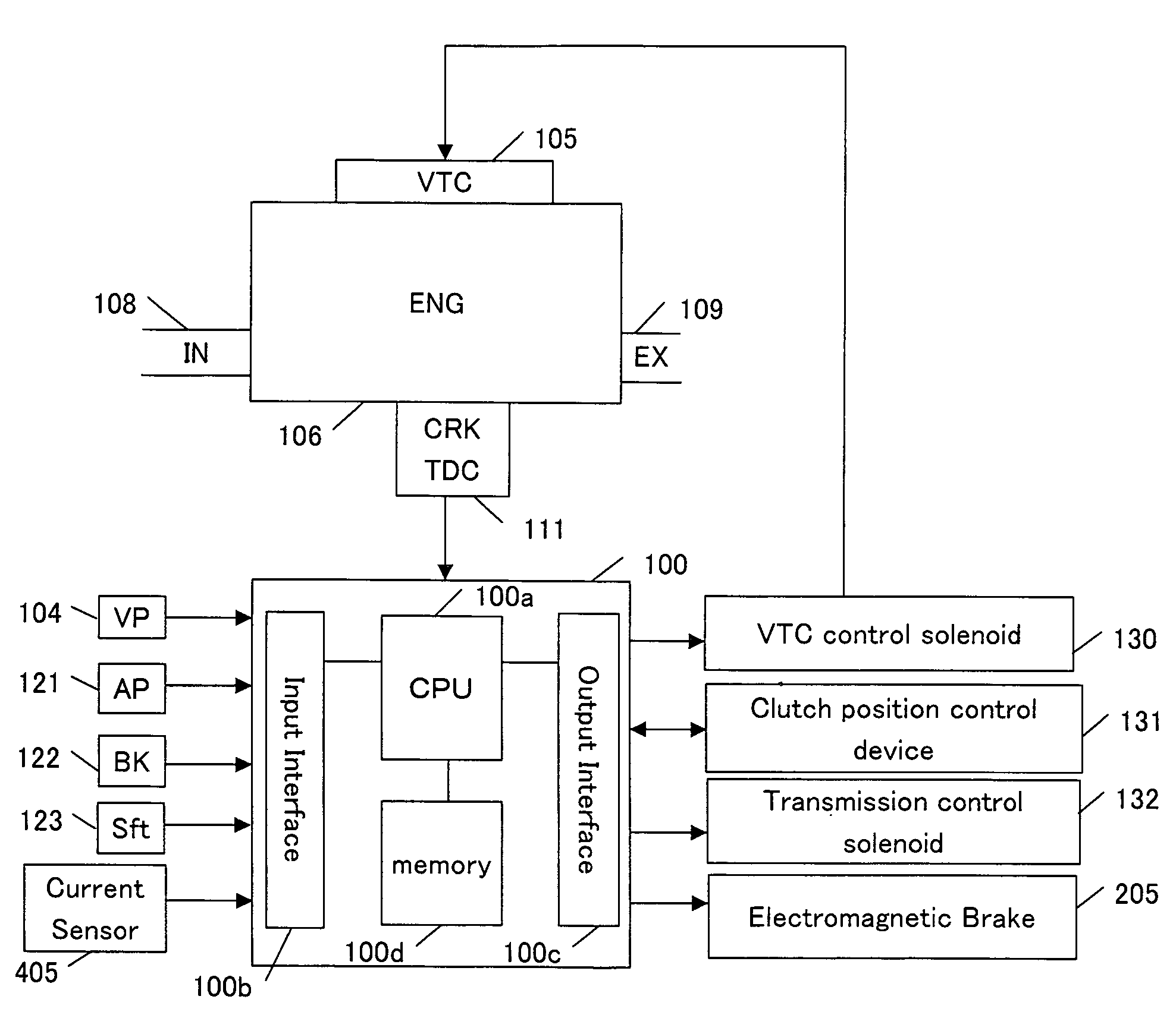
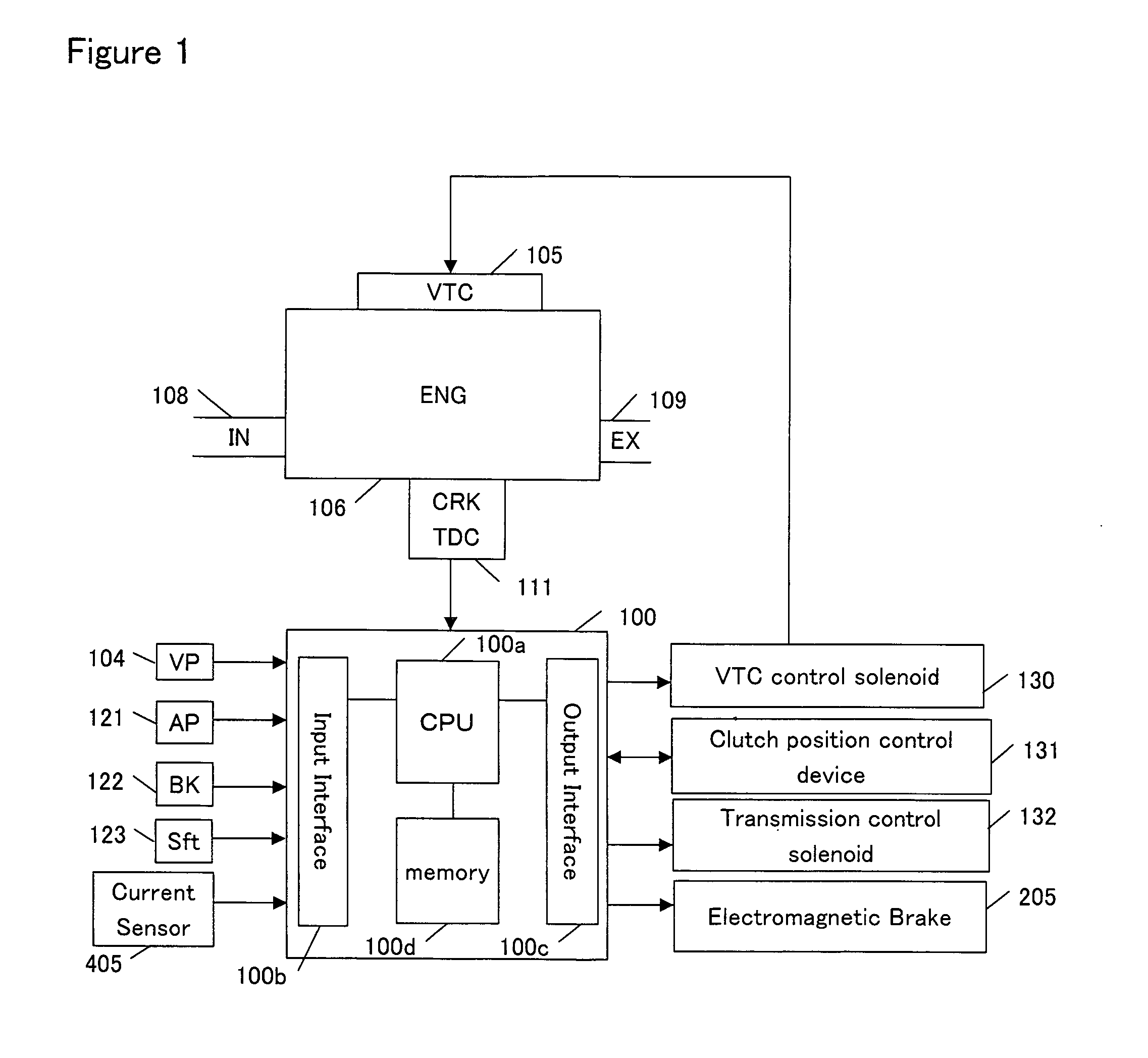
[0036]One embodiment of the present invention will be described referring to the accompanying drawings. FIG. 1 is a block diagram showing an improved automated manual transmission, an engine and peripheral devices for a vehicle in accordance with one embodiment of the present invention.

[0037]An electronic control unit (hereinafter referred to as an ECU) 100 is essentially a computer and comprises an input interface 100b for receiving data sent from each part of the vehicle, a CPU 100a for carrying out operation for controlling each part of the vehicle, a memory 100d including a read only memory (ROM) and a random access memory (RAM), and an output interface 100c for sending a control signal to each part of the vehicle. One or more programs and data for controlling each part of the vehicle are stored in the ROM. One or more programs for implementing the invention can be stored in the ROM. The ROM may be a rewritable ROM such as an EPROM. The RAM provides work areas for op...


PUM


Abstract

A transmission comprises a first transmission mechanism and a second transmission mechanism. When a clutch is in an engaged state, the first transmission mechanism transmits a driving force from the engine to the axle shaft. When a clutch is in a disengaged state, the second transmission mechanism transmits a driving force from the engine to the axle shaft. An electromagnetic brake is connected to the second transmission mechanism. A braking force generated by the electromagnetic brake allows the transmission of a driving force by the second transmission mechanism. Thus, a driving force is continuously provided even when the clutch is released for a gear change operation.

Description

BACKGROUND OF THE INVENTION[0001]The present invention relates to a transmission that transmits a power of an engine to an axle shaft and, in particular to a transmission that can transmit a power of an engine to an axle shaft during a gear change.[0002]At present, an AMT (Automated Manual Transmission) is available. The AMT has better fuel efficiency than an AT (Automatic Transmission) and is easier to operate than a MT (Manual Transmission). The AMT has almost the same structure as the traditional MT. In the AMT, a gear change (gear shift) and a clutch operation are implemented by a hydraulic actuator or an electric actuator in accordance with a signal from an ECU (electronic control unit), instead of a driver. According to the AMT, fuel efficiency can be improved.[0003]Similarly to the MT, the ATM needs to disengage the clutch during a gear change operation. If the clutch is disengaged, a driving force is not transmitted from the engine to the axle shaft. For this reason, smooth ...

Claims


Application Information

Patent Timeline
Patent Type & Authority Patents(United States)
IPC IPC(8): B60W10/00
CPCB60W10/02B60W10/11B60W30/19F16H61/0437F16H3/12Y10T477/693F16H2003/0818F16H2061/0425F16H2312/06Y10T477/6414
Inventor YASUI, YUJI
Owner HONDA MOTOR CO LTD
Why Eureka
Try Eureka